
Delivering 224 Gbps PAM4 signals will require careful analysis of signal integrity and thermal effects, as well as the development of enabling technologies and new methodologies to achieve clean signals at these data rates.
Industry-leading experts are focused on this topic, developing new technologies as well as products to handle high-speed data, and engaging in interoperability demonstrations at tradeshows, demonstrations of new products for 224 Gbps PAM4 systems, and numerous ongoing panel and webinar discussions. Early designs suggest that several technologies developed for 112 Gbps can be applied to some 224 Gbps systems, but changes will also be necessary in order to address signal integrity and thermal concerns across the board.
Despite the lack of an approved 224 Gbps specification, a selection of silicon and interconnects are already available for testing and transporting this next generation of rapidly moving signals. A newly released white paper explains how 224 Gbps PAM4 systems must differ from their 112 Gbps counterparts in terms of interconnects, what technologies and methodologies could enable new 224 Gbps PAM4 solutions, and what’s available now for test and evaluation.
Challenges for 224 Gbps PAM4
At the heart of the 224 Gbps PAM4 interconnect design challenge are the issues of thermal dissipation, insertion loss, crosstalk, and skew.
As the data rate increases, the power consumption of the silicon increases. As a result, the size of the heat sinks must grow with each new generation. Solutions for 112 Gbps included low profile connectors to fit under the heat sink (optimized for footprint, not performance).
112 Gbps PAM4 designs frequently use near chip connectors (NCCs)—connectors placed next to the ASIC and connected to twinax which links to the front panel, back panel, or mid-board. This approach reduces the overall loss of the channel.
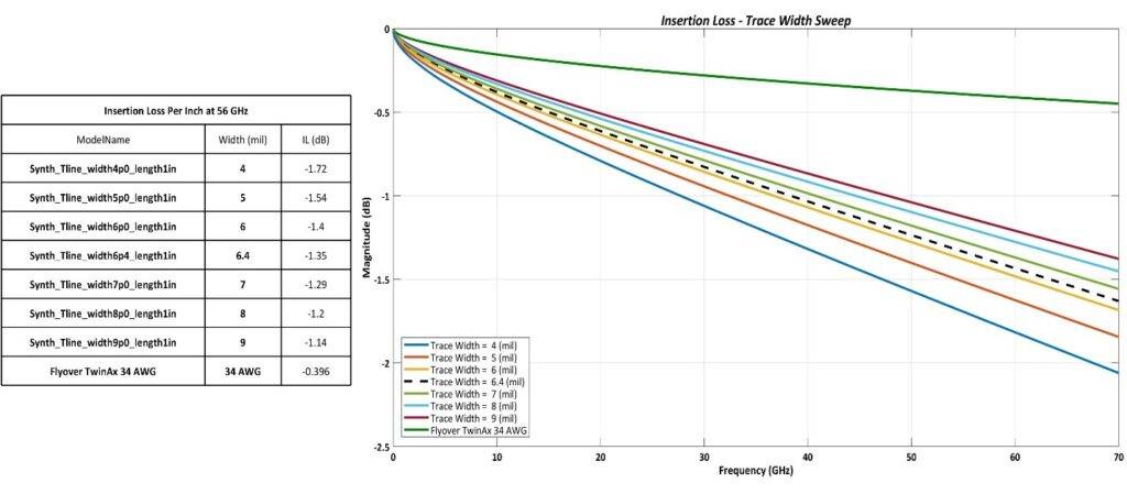
The figure above shows how Samtec Flyover® systems can improve insertion loss by routing signals via ultra-low skew twinax cable versus through lossy PCB. This Flyover approach is expected to also be well suited for many, but not all, 224 Gbps PAM4 system designs.
This graph shows insertion loss (Y axis) plotted against data rate frequency (X axis). The numerous colored lines indicate the performance of various widths of PCB traces at 1 inch of lenght, while the green line tracks an inch of Samtec Flyover system using 34 AWG twinax cable. The graph shows better insertion loss for cables vs PCBs.
Performance and Solutions
As data rate increases, the loss per inch increases significantly. Traditional connections through the BGA ball and PCB will be treacherous to 224 Gbps PAM4 signaling. Even the loss associated with a PCB trace as short as 1.5 inches (as used in both of the 112 Gbps Flyover systems mentioned above) might still be too much for some new 224 Gbps systems. So, what can be done?
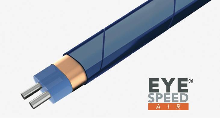
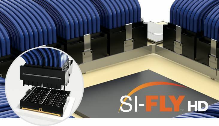
Read the white paper Achieving 224 Gbps PAM4: Interconnect Challenges, Advantages, and Solutions to find out. Learn about the differences between co-packaged and near chip connector approaches, the new connectors being developed to support 224 Gbps, see an analysis of 224 Gbps connector performance, including insertion loss, return loss, crosstalk, and skew. The white paper closes with an overview of the new products Samtec has introduced to support 224 Gbps designs, including Eye Speed® Air™ and Si-Fly™ HD.
Also See
Samtec Supports 224 Gbps at DesignCon 2024 – The Samtec Blog
New 224 G Interconnect Family In A Live Product Demonstration – The Samtec Blog


Leave a Reply