PCI Express: Is 85 Ohms Really Needed?
In late April Samtec kicked off its series of gEEk® spEEk webinars. gEEk spEEk allows engineers to interact with Samtec’s engineering leaders and SI experts on a variety of selected SI-related topics.
Samtec SI Engineer Steve Krooswyk presented one of the first webinars entitled “PCI Express: Is 85 Ohms Really Needed?” This webinar was well-attended and incredibly well-received.
I spoke to Steve about the presentation and why he selected this topic, about the PCIe 85 ohm requirement, and about PCIe 85 ohm over cabling, to name a few topics. The following is a summary of our conversation.
DANNY: Steve, can you give us a brief overview of this webinar? Why did you select this topic?
STEVE: High speed systems today face many simultaneous impedance requirements that must be achieved in the same stack-up – differential impedances at 100 ohms for ethernet, USB at 90 ohms, PCIe at 85 ohms, and a myriad of single-ended DDR requirements. We want to follow the specification, selecting components and routing traces at the correct impedance. However, sometimes there are hurdles – the preferred component is not available in 85 ohms, or the upstream package is yet another impedance. We want to follow this mantra of 85 ohms for PCIe, but it may not be so easy. What can we do, and what does the specification say?
DANNY: Is an 85-ohm connector required for PCIe?
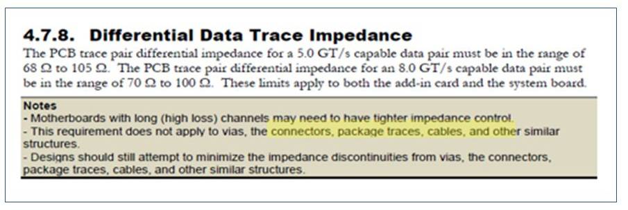
STEVE: Lets go directly to the specification. About the PCIe 85 ohm requirement, the specification says “This requirement does not apply to vias, connectors, packages, cables, and other similar structures” PCI Express Card EletroMechanical Specification Revision 4.0 version 1.0, section 4.7.8.
Connectors outside of 85 ohms are acceptable, and in fact this is common. For short durations, the contacts are exposed to air (like CPU sockets), which raises the impedance. These short excursions will be higher than 85 ohm, but play no detrimental role in the return loss. In fact, it is quite common to observe 110 ohms on compliant Gen3 and Gen4 connectors.
DANNY: On the PCB, is 85 ohm routing required?
STEVE: It is required for the case of interoperable systems and cards that follow the CEM (Card EletroMechanical) specification – ensuring a matched impedance for any mated device.
All other systems — with any number of connectors or cables — may use any PCB impedance. Many packages and connectors are designed to support multiple I/O and will have an impedance of 100 ohms, or even 93 ohms as a balanced compromise. I recommend to review and determine what impedance may be optimal for your specific design.
It is becoming more common to see 93 ohm routing, but it is not unreasonable to continue with 85 ohm routing alongside higher impedance packages and connectors. Lower PCB impedance does tend to have some advantages including lower losses, better matching to dense BGAs, and more tolerance to impedance variation to name a few.
DANNY: Would PCIe over cabling require 85 ohm twinax?
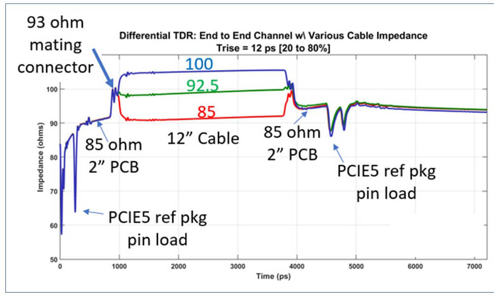
STEVE: It is tempting to select cable impedance to match what is used on the PCB. However there are a couple of anecdotal considerations. First, higher frequency reflections are a greater function of the mating connector impedance than the PCB itself. If an incoming signal experiences an increase from 85 on PCB up to 93 ohms for a given connector, it is best to remain at 93 ohm and not create new reflections by following it with a decrease to 85 ohm cable.
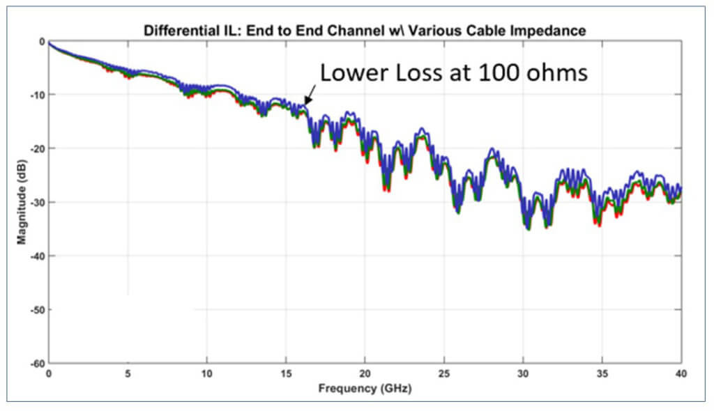
Secondly, the relationship between impedance and loss is inverse of the PCB relationship. That is, higher impedance cable has less insertion loss whereas higher impedance PCB would otherwise be more loss. The loss difference between 85 and 100 ohms is as much as 14%, and is explained in the actual geometry of the twinax. This is the experience for Samtec twinax eyespeed cable and may not be the experience for all cable suppliers.
Ultimately, cable impedance choice depends on the priorities for your system. If insertion loss is the greatest constraint, then 93 or 100 ohm cable is the best choice.
DANNY: Excellent! Any closing comments?
STEVE: Hopefully our readers are enabled to review their specific design, select the optimal impedance, and not be constrained to 85 ohms. Remember, the specification only requires 85 ohms for the PCB routing when using the interoperable CEM slot. When it comes to connectors, cables, packages, and PCB routing to other connectors, the specification permits any impedance that is optimal for your design.
This summary only scratches the surface of everything covered in the webinar. If you want to check out the entire presentation and discussion, here’s a link to the “PCI Express: Is 85 Ohms Really Needed?” gEEk spEEk webinar.
Here’s a list of upcoming gEEk spEEk webinars as well as links to the previous webinars if you want to listen to them.
Just adding my opinions on this subject based on 20 years of SI work.
100 Ohms was usually a target impedance for most differential signaling (PCIX, SAS, SATA, and a bunch of others.) It made sense to have 2 50-Ohm traces (50 was a good round number for most VNAs, too.
I believe Intel came up with the 85 Ohms target (about 20 years ago) for 2 main reasons.
1. 100 Ohms was had to achieve on PCBs at that time since trace widths were greater than 6 mils usually. To get to 100 Ohms, we used to have to void GND planes under traces to use a secondary GND further away.
2. If you built a receiver with 2 50-Ohm resistors in series (to get your 100 Ohms), you would usually have at least 5 to 10 picoFarads of die capacitance in parallel to each 50 Ohm resistance, which would look closer to 37 to 38 Ohms at the rise times of the new Gbps signals. So, they figured that 85 Ohms would be a better match to the traces.
So, 85 Ohms became the PCIe standard – but it is not that relevant today with smaller die capacitances and 3 mil traces.
As the article states, the loss at 85 Ohms is usually greater than the loss at 100 Ohms for the PCB too, not just the cabling. But that has changed with low-loss dielectrics they didn’t have in 2000 for most commercial PCBs. Yeah, there were exotic materials (Teflon), but only special needs for microwave and military applications could afford to use them.
Add to that HVM (High Volume Manufacturing) of traces on PCBs have historically produced tighter tolerances for 85 rather than 100 Ohms, and sometimes it is better to be consistent (match those impedances) in your design than to achieve an ideal value.
93 Ohms comes about because connectors are difficult to design to get down to 85 Ohms, a mid-target of 93 also allows the connector to be dual-purpose for both 85 and 100 Ohm systems, reducing the cost of making 2 different versions.
PCIe on PCB requres 85 Ohm diff. impedance of the traces as result of bigger losses in copper, skin effect and rougthess, than in a HS dielectric material on the high frequencies. Two parts of the trace parameters impact to diff. impedance. There are single end trace impedance and distance between traces in the pair. If trace width is increased for the metal losses reduction, the single end impedance will be reduces. For sample: 45-46 Ohm single end traces impedance can be used in diff. pairs for aciving 85 Ohm diff. pair impedance with predifined traces’ gap.