Break Out Region Design By Inspection
Samtec gEEk® spEEk is a series of free online seminars, covering a wide-range of topics, all commercial-free. gEEk spEEk allows engineers the opportunity to interact with signal integrity thought leaders and experts like DesignCon Engineer of the Year Istvan Novak, Scott McMorrow, and a number of other Samtec engineering leaders.
Travis Ellis, a Signal Integrity Engineer at the Samtec Wilsonville (OR) Cable Facility, recently presented “Break Out Region Design By Inspection.” The purpose of his presentation was to discuss connector-to-board transitions and common impairments to their performance. I spoke with Travis about his webinar and the key points discussed.
DANNY: Travis, why did you select this topic?
TRAVIS: I chose this topic because I’m passionate about it. Over my career I’ve had the opportunity to spend a lot of time optimizing systems. Unfortunately I’ve seen many systems fail to live up to expectations, and almost always it has boiled down to an implementation failure at the break out region (BOR).
DANNY: Can you elaborate?
TRAVIS: A good example of this was a designer at a network company that uses our Flyover® cable system. The channel performance was degraded and the overall loss was double what was expected. The root cause for this loss was the break out regions were not using the tuned design we provided. It also was degraded by their ASIC BOR. These were really poorly done and a 100 ohm transition was only 80 ohms.
We’ve also seen this with other customers where the breakouts in the channel aren’t optimized. With our low loss Flyover cable solutions these become even more important.
When using Flyover cable systems the end-to-end loss is significantly lower, often 50% or even 35% of what was originally in the channel. The loss was concentrated between the two connectors and their BORs. Once the loss is minimized the reflections caused by a poor breakout are no longer attenuated by the channel loss.
With a poor BOR you can have a lot of ringing in the insertion loss due to these undamped reflections. My hope was to highlight the risk and also give designers some simple tools to assess their BORs.
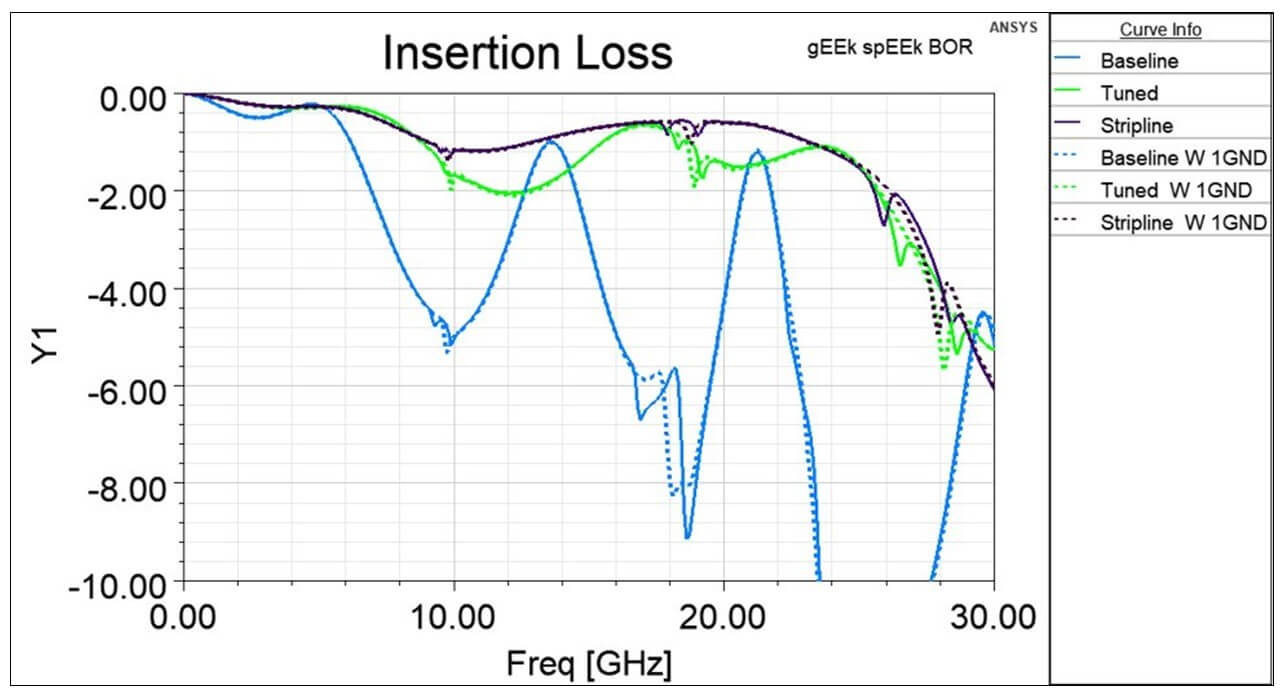
The graph below illustrates why break out regions are important. The blue trace is from a customer-supplied design with poor tuning. The purple and green traces are after the design has been optimized. The purple trace is the best — it has the lowest cross talk and return loss.
DANNY: What were the main points you were trying to communicate in the webinar?
TRAVIS: First, it’s important to have well-optimized BORs. Second, how does a designer visually assess a break out region and answer the question “Do I need to simulate this BOR?” And third, Samtec’s expertise in designing BORs is unmatched in the connector industry.
DANNY: To that last point, can you share any examples of what we can offer a designer to help them succeed?
TRAVIS: We have developed several breakout design guides to help our customers succeed with our products. Two examples are our BOR design guide for SEARAY™ and our FireFly® Flyover cable products.
With our newer products, we’ve taken this a step further and co-developed the breakout regions while designing the connector. For example, NovaRay® and Si-Fly™ are new both products that have thorough documentation for successful break out region design. The beauty of these design guides is that they provide a solid first order solution, and any subsequent full wave simulation work is much more efficient.
DANNY: What questions or other discussion points came up from the audience that were worthwhile to share here?
TRAVIS: Crosstalk wasn’t specifically addressed in this presentation but it continues to be the next hurdle we need to address. The via field can dominate cross talk performance, so our connectors are designed to yield the best overall performance taking the BOR into account.
We’ve had designs where the crosstalk for the entire channel is only around 1%. But when a new breakout is introduced somewhere in the channel — typically with a new thicker substrate with signal vias traversing the entire stack up — suddenly the cross-talk jumps to 5% or more. This is due to the coupling between vias in the pin field. All of this can be mitigated if the via field is carefully design with enough ground vias to provide the necessary isolation.
Here’s a link if you want to watch in Travis’ Break Out Region Design By Inspection gEEk spEEk webinar.
DANNY: Thanks for sharing Travis, this is good stuff. Who should a reader contact if they have questions?
TRAVIS: Thanks for the opportunity to share. If a reader has questions they can contact the Signal Integrity Group.