COPLANARITY AND STENCIL THICKNESS STUDY
Samtec and Phoenix Contact recently completed dual studies that show when PCB processing requirements dictate using a 0.10 mm (.004”) stencil, the coplanarity requirements for most connectors can be relaxed to a maximum of 0.15 mm (.006”). In other words, Samtec and Phoenix Contact both successfully soldered PCB connectors with 0.15 mm coplanarity using a 0.10 mm thickness stencil with optimized apertures.
CHALLENGE FOR DESIGNERS
Designers know well that fine pitch components – i.e., sub 1.00 mm pitch – require thin stencils. The thicker the stencil, and therefore the greater the volume of solder paste, the greater the chance of solder bridging. Many designers will not specify a connector whose coplanarity specs exceed the thickness of the stencil. For example, if they are using a 0.10 mm thick stencil, they will not specify a connector whose coplanarity specs exceed 0.10 mm.
This is a conundrum for designers because tight size/coplanarity specs may limit the number of connector options available to them. This is especially true for larger pin count, standard pitch PCB connectors – e.g., 2.54 and 2.00 mm pitch connectors — because the coplanarity can creep above .10 mm.
Usually, connectors with fewer pins and finer pitches have tighter coplanarity specs. Conversely, connectors with more pins in a row, especially with more standard centerlines (i.e., larger), are more likely to have slightly higher coplanarity specs. Based on the results of this study, designers now have many more connector product choices available to them because they can use a thinner stencil and still achieve reliable solder joints.
This method also eliminates the need for more expensive stepped stencils.
SCOPE
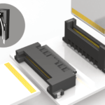
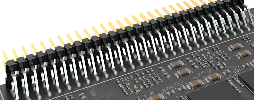
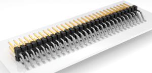
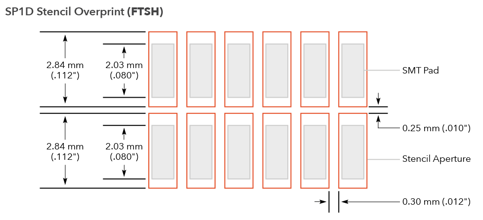
Samtec’s Interconnect Processing Group (IPG) soldered three (3) connector series using a 0.15 mm stencil with 1:1 apertures. By 1:1 we mean the aperture is the same size and shape as the pad. The IPG also soldered three (3) connector series using two (2) variations of a 0.10 mm stencil with enlarged apertures. Phoenix Contact performed a similar study using a 0.10 mm stencil with the optimized aperture design. Below is one of the optimized apertures, for a Samtec FTSH series 1.27 mm pitch terminal strip. Connectors were built and measured, then sorted to find a coplanarity range suitable for this study (i.e., coplanarity of 0.10 mm – 0.15 mm).
The product series included in the report are FTSH-DH (SMT, dual row horizontal orientation), MMT-DH (SMT, dual row horizontal orientation), and TSM-DH (SMT, dual row horizontal orientation).
The complete part numbers are:
CONCLUSIONS AND RESULTS
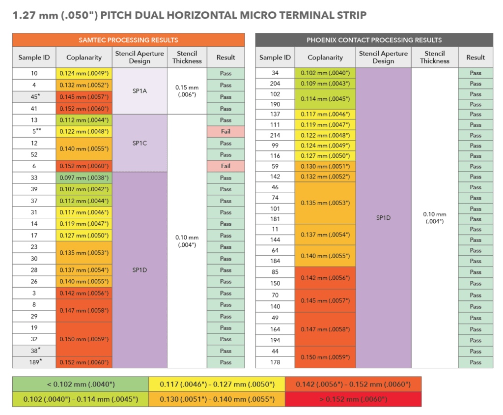
Between Samtec and Phoenix Contact, a total of 135 connectors were soldered using a 0.10 mm stencil with optimized apertures, and all passing and meeting at least IPC-J-STD-001 Class 2 criteria for a 100% yield. The optimized aperture is slightly larger than the pad. During reflow the overprinted solder paste is drawn to the concentrated heat of the copper pad and component lead. The overprint is minimal and does not result in solder balls on the PCB surface due to the surface tension of the molten solder being sufficiently strong to maintain the volume’s cohesion. See below for the results of one of the connectors (Samtec FTSH series) soldered by aperture type. Here is a link to the complete report to view the results for all three product series, by each aperture type (see pages 6, 8, and 10).
LEARN MORE
Here’s a link to the complete report.
If you have questions please contact the Samtec Interconnect Processing Group (mailto:[email protected]). IPG is an in-house staff of Engineers to field all of your interconnect processing concerns. IPG can assist you in improving the overall processing and manufacturability of your board as well as helping lower its total applied cost.
Here are other IPG-related links that may be of interest:
- Dissimilar Metals And The Risk Of Galvanic Corrosion in Mating Connectors
- Interconnect Susceptibility To Galvanic Corrosion
- Multiple Connector Alignment On Mating PCBs
- Interconnect Test Report Frequently Asked Questions
- Advice On Selecting and Processing Connectors
- Guidelines To Ensure Electromagnetic Immunity In Connectors
- Guidelines For Paste-In-Hole Reflow Processing
- Fretting Over Fretting Corrosion
- Best Practices For Connector Models
- FAQ Interconnect Test Reports