Multiple Connector Alignment On Mating PCBs
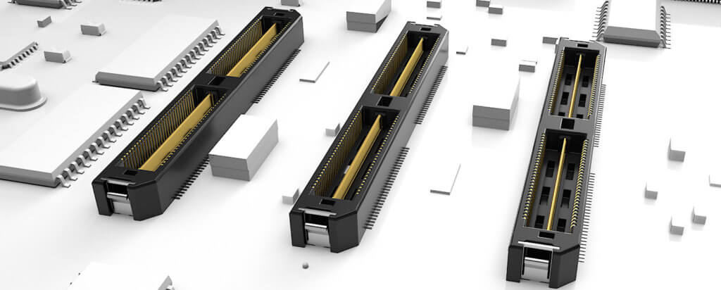
Design and Processing Engineers frequently contact our Interconnect Processing Group (IPG) to discuss multiple connector alignment issues on mating PCBs. Our standard response is “it’s easy, don’t worry about the alignment, and we recommend you use as many mated connector sets as possible.”
OK, I’m lying.
The first part – that IPG receives a lot of inquiries – is true. The second part – it’s easy – is not 100% true. At times it can be complicated. When using multiple connectors per board, there is a higher potential for misalignment. It can be hard, like playing first base.
Anyway, here are eight tips, thoughts, suggestions, and ideas, on how to process multiple connectors on a board, where the connectors need to be mated simultaneously. We hope the following will help and possibly improve your design.
1. Do The Math On Tolerances Calculate the PCB and connector tolerances and see if everything will line up. PCBs usually have much bigger tolerances than connectors; this is true for any connector, not just Samtec’s. The smaller the connector pitch, the more likely the tolerance/math won’t add up. And it should be a warning to you if a connector company isn’t willing to give you allowable misalignment. You can find our misalignment allowances on our Product Specification sheets. Here’s an example of a Product Specification sheet; see the bottom of page 3.
2. The Bigger The Better I know this is obvious, but use the biggest connector system possible. Examples include bigger centerline (2.54 mm is nice), through-hole, a taller mated connector set, sockets with contacts that have multiple points of contact, chamfered lead-ins, alignment features, etc.
3. Check The Footprint I’m sorry to be Captain Obvious again, but make sure and use recommended connector PCB footprints and stencil designs. All of our PCB footprint prints are located on our website; here’s an example of a footprint.
4. One Connector? If your design incorporates two micro pitch, SMT connector sets, can you make it work with one high density system, or with one longer connector set with the same number of total I/Os?
5. Add A Cable Assembly If your design requires two mezzanine connector sets, is it possible to use one mezzanine set and make the other a cable assembly? It’s a bit more expensive but it will greatly alleviate the alignment issues.
6. Float Depending on the tolerance build-up, can you use connectors that allow for float on the X and Y axis? For example, check-out the Samtec FT5 and FS5 series.
7. Secondary Processes Since PCBs have the bigger tolerances, you can consider using secondary processes to improve the manufacturability of the PCB. Examples include making larger pads and then reducing the size, or using lasers to create alignment holes, or laser cut the boards to align with critical dimensions. Contact your PCB manufacturer about these processes. Unfortunately, this can become an expensive option, so consider numbers 1-7 above first.
8. Call IPG Samtec’s Interconnect Processing Group has tons of experience helping our customers with challenges like this. We understand that every design is different and has its own unique challenges, and you’ll be talking to engineers who understand connectors and processing.
IPG is an in-house staff of Engineers to field all of your interconnect processing concerns. IPG can assist you in improving the overall processing and manufacturability of your board as well as helping lower its total applied cost. You may contact IPG directly by emailing [email protected].
Check-out this Application Overview of suggestions on processing multiple connectors to mate two printed circuit boards.
Related Links:
- Challenges of Aligning Multiple Connector Sets
- Dissimilar Metals And The Risk Of Galvanic Corrosion in Mating Connectors
- Interconnect Susceptibility To Galvanic Corrosion
- Interconnect Test Report Frequently Asked Questions
- Advice On Selecting and Processing Connectors
- Guidelines To Ensure Electromagnetic Immunity In Connectors
- Guidelines For Paste-In-Hole Reflow Processing
- The Facts Of (Extended) Life
- Fretting Over Fretting Corrosion
- Best Practices For Connector Models
- FAQ Interconnect Test Reports