Samtec provides a wide variety of test data for nearly every product we offer. Our goal is to provide thorough, straight-forward, easy-to-access data so you can choose the best product for your application.
We field countless questions about interpreting data in test reports. I asked Mark Shireman from our Engineering Support Group to list five common questions we receive about our interconnect test reports. In addition, he provides a few tips and comments to help interpret the data in our test reports.
1. What is the current rating of a connector? How many amps will it handle?
(CCC, or Current Carrying Capacity)
This is a very common question. It’s extremely rare in the connector world that a manufacturer tests the connector the way a customer uses it in his application. There are simply too many design and application variables. For example, many product specifications list a current rating for a single pin, but few customers have only one pin powered.
Our test reports provide multiple configurations with a variety of pins powered to support a broad range of applications. We typically power and test the following configurations at various ambient temperature:
- 2 pins
- 4 pins
- 6 pins
- 8 pins
- maximum pin count (e.g. 100 pins in 2 x 50 configuration)
After collecting the data, we illustrate them graphically. For examples, Figures 1 and 2 show how we report current rating, ambient temperature, and temp rise.
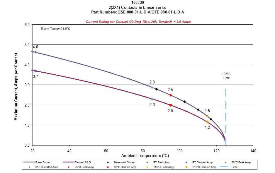
Figure 1: Current Rating vs. Ambient Temperature
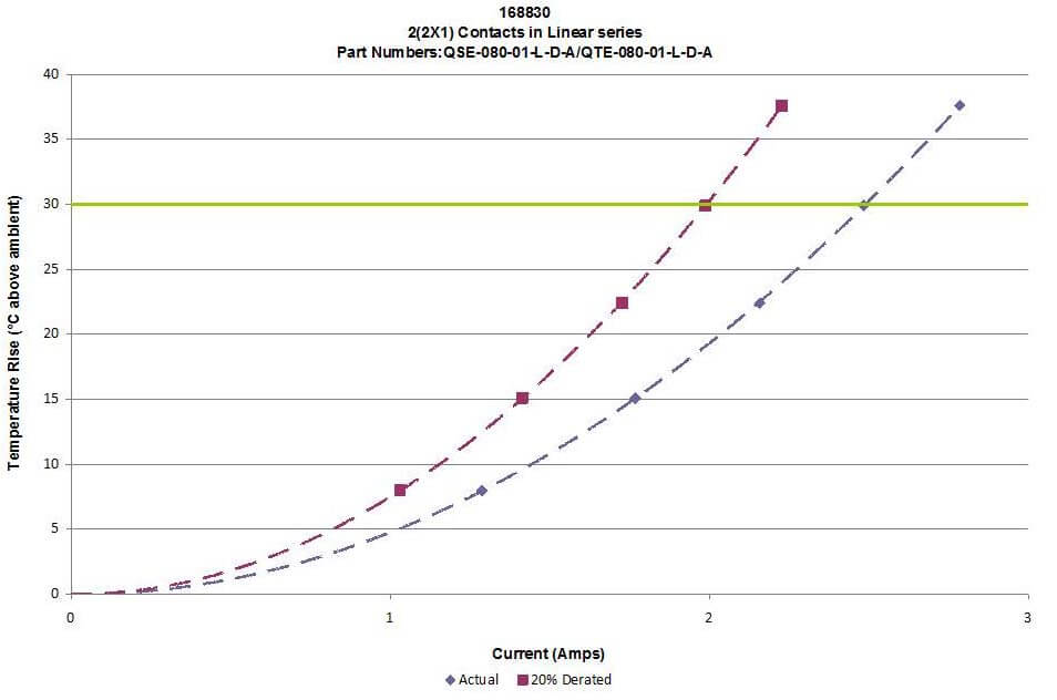
Figure 2: Temperature Rise (above Ambient) vs. Current
2. How many cycles will this connector handle?
(Durability / Life Cycle Tests)
Our typical answer is “it depends.” Our connectors are not tested to failure. We typically test our connectors from 25 to 100 cycles depending on the connector design. Failure is best determined by the application and we are always willing to discuss custom testing scenarios.
Low Level Contact Resistance (LLCR) is measured initially and after exposure to mechanical stress (cycles), thermal shock, and cyclic humidity. Our goal is stable LLCR throughout all of the stresses, and we will typically not release a product for sale if there is more than a 15mΩ delta (change in resistance) from the initial value. Many customer applications are easily able to handle much more resistance than this, and this is why we say “it depends” when addressing cycle life.
Samtec Extended Life Products (ELP) are designed to withstand extreme applications and are tested to a higher number of cycles. See Figure 3 for a flowchart showing typical steps in the durability testing process.
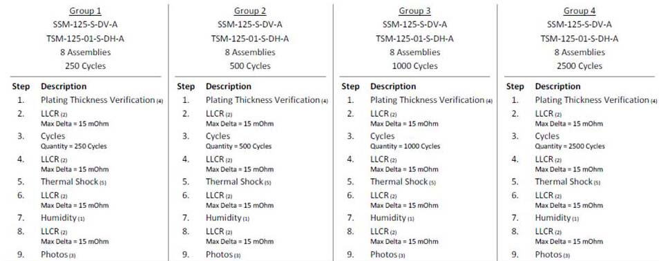
Figure 3: Example of Extended Life Product Test Flow
3. What is the force required to mate or un-mate a connector set?
(Mate, Un-Mating Force Tests)
Configuration, number of pins, number of rows, and plating can drastically impact the required mating and un-mating force. We typically test the connector set under three conditions:
- the smallest number of positions offered
- the mid-point number of positions offered
- the largest size number of positions offered
After cycling and thermal stress tests, we establish a curve to fill-in the mating and un-mating force required for positions not tested.
This testing approach is more robust than simply extrapolating the mating/un-mating force of a single pin connector and then multiplying the force by the number of pins in a larger configuration. That approach is simplistic and does not account for other factors that can affect mating forces. See Figure 4 for mating and un-mating data for one interconnect system tested at 10, 30, and 50 positions.
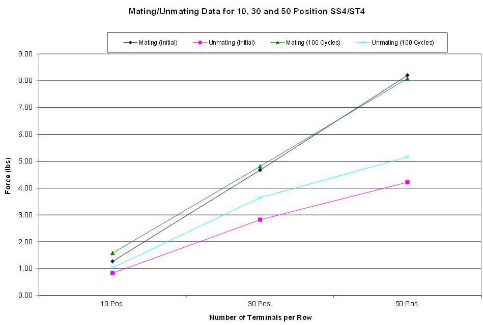
Figure 4: Mating, Un-Mating Force Comparison
4. Do you test to my specifications?
(Vibration/Shock Specifications)
Since we can’t test every different shock and vibration specification available, we test to EIA-364. EIA-364 specifications are common to general application usage and not for a specific industry or segment, such as military or automotive, unless otherwise agreed upon. Similar to durability testing, we measure LLCR before and after stressing, as well as for signal interruptions (event detection).
It is worthwhile to note that we use external mechanical fixtures and test in a manner to eliminate relative motion between the mating interconnect system. This allows us to focus the vibration stress on the contact interface, thus avoiding fretting corrosion. Figure 5 shows two examples of typical vibration and shock test setups.
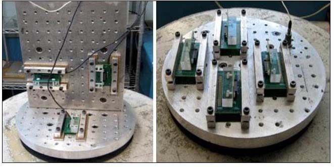
Figure 5: Example of Shock/Vibration Test Fixtures
We test by securing the mating socket and terminal interconnects to the test fixture, again, so the stress is focused on the contact interface. While this method does not account for the relative motion and movement of the boards in the completed assembly, it does allow us to confirm the integrity of the contact interface. As previously explained in question #1 above (CCC), the sheer number of variations of designs and variables make it impossible to test every possibility.
5. How does Samtec establish a voltage rating?
(DWV (Test Voltage) Testing)
Here again, the voltage requirements are typically application and industry specific. Our test data covers a variety of requirements and potential applications, allowing customers to evaluate performance across a number of voltage ratings.
World-wide safety regulations often require safety levels above and beyond working voltage ratings. Our working voltage is our “Voltage Rating”, but this is de-rated at 1/3 of the DWV.
Final Thoughts
As mentioned previously, the answer to most questions about connector specifications is that it depends on your application, the connector you choose, and the plating option. Our methods and reporting are designed to give you as much useful information as possible, but ultimately testing a connector in your application will result in the most accurate simulation.
The best place to start your journey is on a connector test report.
You can find a complete listing of product test data on each product page. For example, here is a link to the test data available for our SEAF Series.
Note we list seven categories of test reports in the left hand column, and numerous reports in each of those categories. You can also contact our engineering support team at [email protected].