Processing micro pitch edge card connectors is easy, just like playing first base. Of course we know that’s a lie — manufacturing challenges increase as connector pitches decrease.
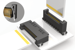
Samtec recently released a 0.50 mm pitch edge card socket. The new MEC5 series (in vertical and right angle designs) is the industry’s first .5 mm pitch edge card socket with a justification beam. This socket meets the demands for higher density and bandwidth, while also optimizing cost. It’s PCIe Gen 4 compliant, and is available in vertical and right angle configurations.
In this article and in the video above, we share the Interconnect Processing Group’s recommendations to increase the likelihood of a successful design. The guidelines I’m going to discuss are not required, but adhering to them will increase the likelihood of success. Samtec’s Interconnect Processing Group (IPG) is an in-house staff of Engineers who address your questions about interconnect processing issues. IPG can assist you in improving the overall processing and manufacturability of your board as well as helping lower its total applied cost. You may contact IPG by emailing [email protected].
So what’s the issue? Obviously the contacts on a .5 mm pitch edge card socket are small, and the corresponding pads on the mating card are also small. Again, we’re working with a .5 mm pitch solution.
Justification Beam
The justification beam on the MEC5 is designed to shift the card into proper alignment with the contacts for a reliable, accurate connection. Without a justification beam, the .5 mm pitch pads on a card may not align with the contacts on a .5 mm edge card socket. This can be addressed by using a precision-tolerance, or tight-tolerance card.
By tight tolerance, we mean for example that the PCB manufacturer’s tolerances for the overall card width are held to +/- .002”, and the distance from the edge of the card to the pad centerline is also held to +/- .002”. Using a socket with a justification beam, like the Samtec MEC5, allows the mating card to have standard tolerances. Standard tolerance cards provide about a 30 to 50% PCB cost savings and a higher yield, compared to precise, tight-tolerance cards.
While the justification beam helps ensure proper alignment of the contacts to the PCB pads, Samtec recommends designers follow some additional guidelines that will further increase the chances of success.
The Most Important Guideline
The most important guideline is, when mating a card to an MEC5 edge card socket, we recommend that one of the two – either the card or the socket — be free-floating. IOW, if the connector is soldered to a board, then the card that is plugging into the socket should be free-floating, or not affixed to anything else.
Six Recommendations For Processing Micro Connectors
In addition, here are a few recommendations on ways to prevent potential problems:
First, if it’s a requirement that the mating card be screwed to another board or a frame, then plug the card into the MEC5 socket and then tighten the screws. Otherwise both the card and the MEC5 are locked into a position, and the benefits of the justification beam are lost.
Second, don’t design a card with higher I/O requirements to mate with two or more MEC5 sockets. The justification beam on one connector can override the beam on the second connector. Instead, design the card with all of the pads in one interface area and mate this with a higher pin count MEC5 socket. MEC5 is available with up to 300 I/Os.
Third, if the mating board requires another connector set in addition to the MEC5 socket, mate the MEC5 first and mate the other connector set afterwards.
Fourth, we recommend not placing guiderails around the MEC5 socket. Guiderails are usually stronger than the justification beam, so the mating card will be directed by the guiderails, and that could misalign the card and connector. Having said that, guiderails can prevent people from plugging the card into the socket at an odd angle, which brings us to #5 …
Fifth, when plugging the card into the MEC5 socket, make sure to load the card straight down into the socket, so the card is perpendicular to the socket. Inserting the card into the socket at an angle can lead to misalignment of the contacts and pads.
And finally, when plugging the card into the MEC5 socket, don’t plug the card and then try to align the pads and contacts yourself by sliding the card to one side of the connector. Exerting too much force on the card in one direction can misalign the contacts and pads. Simply insert the card into the socket and the justification beam will do the rest.
Following the design recommendations addressed in this blog and video will increase the chances of a successful application. If you need additional information, please contact the Interconnect Processing Group at [email protected].