Samtec works with system architects in the early stages of their design to create solutions for cable management which provide even distribution of thermal load. Using ultra-low skew twinax cable to route signals over the board is a key performance enabler as signal integrity and reach continue to become ever more important in high-speed applications.
I spoke to Aaron Tucker, Samtec’s Engineering Director of High Data Rate Products, about the need for these cable management systems, design strategies, and the benefits of implementing such a system.
DANNY: Why are we talking about cable management and why should system designers now consider cable management in their designs?
AARON: Before the advent of Samtec Flyover® interconnects, system designers managed all high-speed connections through copper traces within PCBs. In order to meet the exponential data rate growth and signal integrity (SI) needs, we moved the high-speed signals into copper cables resulting in substantial signal integrity performance gains. So all was great and the world was good.
But now we have taken what was traditionally a 2-D high speed problem/solution and moved it up and out of the PCB, creating a 3-D high speed problem/solution. If we are working with a 512 differential pair system, there are a lot of cables to now manage in this “3-D” space. For someone who is not used to managing high speed cables, not to mention 512 of them, this could be a rather uncomfortable task.
DANNY: What is the goal, or benefit, of a cable management system?
AARON: The primary goal is to provide guidance and insight on more methodical ways to manage these high-speed cables, and to show designers that we have the expertise and experience to help find the right cable system for their design. We also are trying to show system designers that we understand the challenges they face, such as the SI, low speed/power management, available space, thermals, installation and assembly, and the overall need to incorporate systems into their existing designs and architecture.
We created a video that demonstrates all of these factors coming together to adapt to the OCP Wedge 100S design, with a few tweaks for marketing purposes of course. The take away here is that we took a known design and adapted it to a Flyover connector-based approach. We put together a demonstration that was more than a feasible option for engineers and system designers. We didn’t want a system designer to look at this and say “this is just another marketing demonstration and it will never work.” The goal was to put substance behind it so that a system designer could connect the dots and say “we could get there with this approach.”
As I said before, we have tried to take the key challenges designers face — SI, available space, low speed/power management, thermals, installation/assembly — and incorporate them into this demonstration.
DANNY: Can you describe the system and how it works?
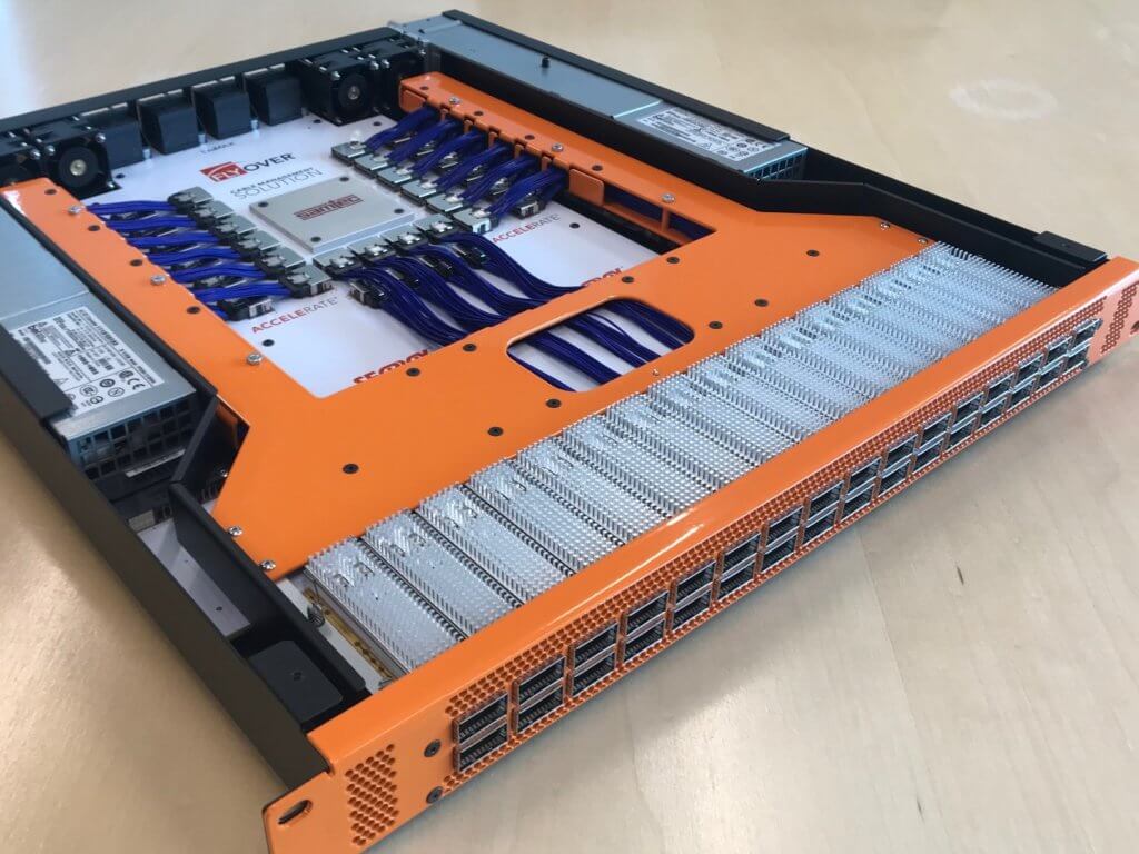
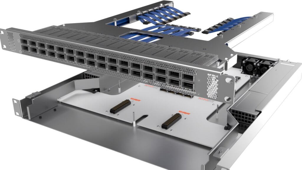
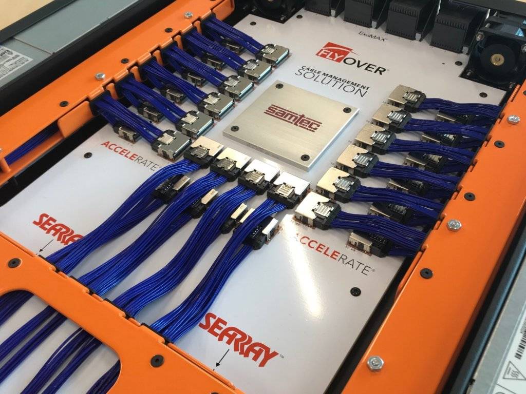
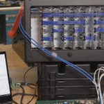
AARON: Sure. With this demonstration we tried to show an approach that is packaged as one solution, where hardware designers could work with their CM’s and Samtec to create a drop-in solution. With the approach shown, we created a mezzanine board that has 32 FQSFP-DD cable/connector assemblies pressed in a belly-to-belly fashion.
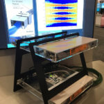
In addition, we have a SEARAY™ high-density array connector system that connects our low-speed signal/power in a board-to-board connection. Next we have a sheet metal tray assembly that attaches to the mezzanine PCB. This tray assembly houses the high-speed cable assemblies and allows us to route them from the front panel to the chip. The front panel is connected to the PCB/wire tray assembly, and the entire system can be attached to the switch for final installation.
Guide posts throughout the tray system provide macro alignment. As the tray/mezz board gets closer to the motherboard we get “gatherability” and micro alignment from the SEARAY connector system. The mating forces remain low since only a couple of connectors are mated during this operation. Next we install the fasteners and secure the tray to the switch chassis.
The final step is to connect all of the Samtec AcceleRate®, ARC6 cable assemblies to the right angle PCB connectors located adjacent to the chip.
DANNY: What does Samtec provide?
AARON: Samtec provides the support, service, and of course the Flyover cable connector systems. Our goal is to make the adoption of Flyover technology as simple as possible for system designers. We work with designers to customize cable assemblies to fit their needs, and provide guidance how to route and install these connectors and cable assemblies. We have tons of knowledge, experience, and overall know-how related to how cables behave. Cables are made of metal and have memory which generates, torques, twists, and resistance to being manipulated. We have taken that know-how and figured out to control the cable in a way that maximizes system performance. We have mechanical, electrical, and thermal experts available to cover all aspects of system design. We are happy to accept 3D models of our customers’ system to model our cables for the perfect fit, and run thermal simulations on the design.
DANNY: Let’s discuss the thermal load; how does this system work compared to a traditional switch?
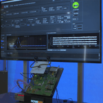
AARON: Keeping in mind our goal was to show a “more feasible” design, we performed a thermal simulation to demonstrate that this approach is capable of achieving “good” thermals.
We assumed a 545 W ASIC Chip using the Broadcom BCM 56990 as the reference, along with 32 QSFP-DD 14 W modules resulting in total system power of 993 W. This design easily achieved the maximum allowable T case temperature for the transceiver of 70° C. For the ASIC junction temperature, this design was at the upper limit due to replacing fans with our ExaMAX® high-speed backplane connectors (this was done for marketing purposes).
Simply adding the additional fans would bring us in-line with the required 105° C spec. The big takeaway here is that we have the ability to create routing symmetry with our cable tray system, resulting in more laminar airflow. This allows designers to push the ASIC further back into the switch, which in-theory gives us a lower ASIC inlet temperature.
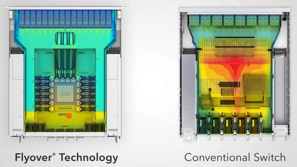
In addition, motherboards can be thinner with the removal of the 512 high-speed traces, meaning we can lower the position of the ASIC and, in turn, increase the height of the heat sink fins, resulting in more efficient cooling of the chip. We actually ran our simulation with the exact same parameters/assumptions for the “traditional” switch and compared it the switch utilizing Samtec Flyover technology. The results were quite fascinating, as the ASIC Tj was 130° C for the traditional and the Tj for the Flyover was 98.5° C.
DANNY: Excellent, great stuff. Who do you contact to get more information on this cable management tray system?
AARON: Contact our High-Speed Cable Group at [email protected].
Leave a Reply