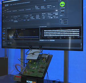
Scott McMorrow, CTO, Samtec Signal Integrity Group, walks us through a live demonstration of a cable backplane and mid-board cable system, both utilizing Samtec Flyover® . Samtec Flyover is most commonly used in mid-board applications, with the cable assembly connector placed close to the chip and direct the signal to the front panel through the cable.
Cable Backplane and Mid-Board Applications
Flyover also allows designers to go from one board to another as a flexible backplane architecture within a rack, as well as being used as a rack-to-rack interconnect. The traditional backplane architecture is retained, but the system offers lower PCB complexity while achieving higher performance targets.
Samtec Flyover can extend signal reach and density to achieve next gen speeds by routing signals via Eye Speed® ultra-low skew twinax cable instead of through lossy PCBs. Eye Speed Cable typically runs four gauge sizes faster than other cables.
Demo Overview
This demonstration of 112 Gbps PAM4 Samtec Flyover cable products is powered by the latest Xilinx test chip for future generation FPGA products, targeted for 7 nm, 112 Gbps SerDes FPGA applications.
It has an advanced digital signal processor that performs FFE and DFE functions. Running through the Samtec connector system, with 1 meter of cable and 14 connector interfaces, it achieves approximately a BER of 1-e7, which is superb for this system. The channel demonstrated has 33 dB loss, from package ball to package ball — from Tx to Rx.
Signal Path
A full 112 Gbps PAM4 chip-to-chip channel routes from a 7 nm, Xilinx 112Gbps PAM4 Transceiver Test Chip; it generates 31 bit PRBS data at 112 Gbps PAM4. These signals travel through precision 2.92 mm RF cable assemblies to a Samtec NovaRay® cable assembly system.
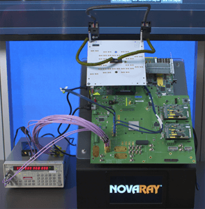
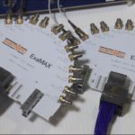
The signals then travel through 12” of 34 AWG Eye Speed Ultra Low Skew Twinax Cable to an ExaMAX® Backplane socket on the back panel. The backplane socket mates to a 30 AWG ExaMAX backplane cable assembly. This cable assembly passes through a lower-cost, and less complex backplane.
The return path repeats itself – the 30 AWG ExaMAX backplane cable transfers from the socket to 12” of 34 AWG ultra-low skew twinax cable, to a NovaRay board level connector, and back to the Xilinx Transceiver Test Chip which processes the data to display BER performance.
The loss for the entire signal path, including all cable assemblies and pcbs, is approximately 33dB. This demonstration has 14 different connector interfaces.
The demo has a higher loss than a typical system because the NovaRay Flyover cable system is not located adjacent to the Xilinx SerDes. In most applications the Flyover system is adjacent to the Xilinx device, so losses are much more reasonable, and the connector system is able to run three or more meters of cable backplane.
Results
The BER performance of our interconnect with the Xilinx test chip is superb. The Xilinx chip uses an advanced A to D front end and D to A back end system with a DSP. In the display of the adaptation taps we see that the DFE and equalization system does not have to work very hard because the Samtec Flyover interconnect has few discontinuities.
Essentially, we are equalizing very short distances inside of the connectors and the transitions into the cables. Otherwise, there’s almost no reflections; it’s a very flat, clean system. This enables us to achieve a 1e-7 BER without Forward Error Correction (FEC), or what Scott likes to call a “FEC-less” operation.
We see the sampled eye in the slicer for the Xilinx device, showing extremely good performance and well-opened eyes with the equalization.
Leave a Reply