Odd Connectors That For Some Reason Are Popular
One of our most popular product lines is two-piece board stacking connectors, what we call “Flexible Stacking.” If a designer is not familiar with our capabilities, I tell them that we have more ways to connect two or more boards than any other connector company. By that I mean we have tons of pitches, pin counts, stack heights, orientations, and combinations of connectors. Put another way, we have more design flexibility than Bubba has shrimp.
This variety and design flexibility also leads to some pretty odd connectors for some pretty unusual applications. While these odd connectors are not our biggest sellers, they have been a God-send for designers who face an unusual design-around challenge. This is the first blog in a series that highlights some of these odd connector systems.
Bottom Mount Socket Strip
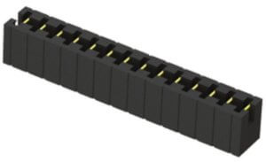
The BSW series is a socket strip on .100” pitch, designed to mate with .025” (0,64 mm) square post terminal strips, or “headers.” What’s odd about a BSW is you solder the connector tail and plug the mating terminal strip pin into the same side of the connector. Imagine a standard vertical, through-hole socket strip, but the tail, which is usually straight and soldered into a plated through-hole on the PCB, instead makes a 180° turn and runs parallel to the plastic body.
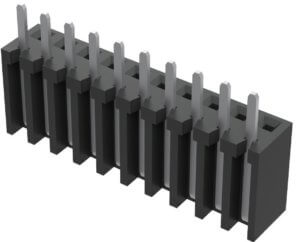
These “bottom mount” socket strips are designed for soldering the connector and plugging the mating terminal strip from the same side of the board. Why would a designer want this? The most common applications are having all components on the same side of the PCB, or placing the mating PCBs very close together (IOW, it’s extremely low profile), or for certain high-temperature or harsh soldering conditions.
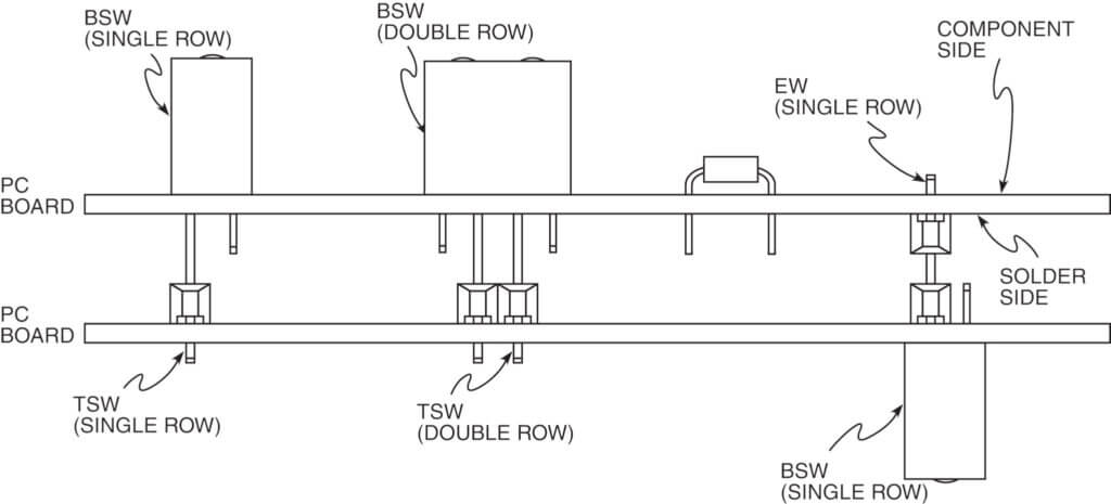
Here’s a link to the recommended PCB layout of a single row BSW if you want to see how it works.
A .025” Square Post Terminal Strip That Is Not Really .025” Square
Samtec’s basic .025” square post through-hole terminal strip (TSW series) has 28 different lead styles for just about every stack height in the known universe. But one of these — lead style 26 — is like no other .025” square pin in the industry. That’s because the post of that pin (that plugs into the mating socket strip) is .025” square, but the tail (that is soldered into the through-hole of the PCB) is .018” (0.46 mm) coined.
TSW style 26 pins allow designers to plug into standard .100” (0.64 mm) pitch socket strips, but the .018” (0.46 mm) coined tail requires a .024” (0.61 mm) diameter PCB plated through-hole instead of a.040” (1.02 mm) diameter PTH for standard .025” square posts.
This added space gives designers more flexibility in designing and routing traces on the board. BTW, here’s a chart of recommended PCB hole sizes for different size connector tails.
Multi-Position Shunts
I can’t believe I’m writing about shunts. I think this is a first. But we have a product that is a multi-shunt. Instead of one shunt to divert a circuit, the MNT is a multi-row shunt that allows designers and technicians to shunt several circuits in a row. Why would somebody want to do this? I don’t know, but we sell millions of these things. And they are available with up to 20 positions (shunts), with either gold or tin plating.
Stayed Tuned …
We have a lot of these odd connectors that solve specific design challenges, and I’ll be writing about more of these in the near future.