
How to Improve Signal Integrity for 224 Gbps Test Systems (Part 2)

In Part 2 of the blog series “How to Improve Signal Integrity for 224 Gbps Test Systems” we’re going to proactively address, at a high level, common questions that occur when examining key SI principles for high performance applications, especially for 224 Gbps test systems. For a deep dive on these topics, please review Samtec’s published paper: Realistic Use Cases for Edge, Angled and Veritcal Launch Connectors Up to 100 GHz. Also, here’s a link to Part 1 in case you missed it.
COMMON QUESTIONS
1) What is a Test Fixture and its Signal Path?
The test fixture usually consists of a combination of connectors, cables, and printed circuit boards (PCBs). The test fixture is used for a consistent, repeatable test setup and therefore consistent, repeatable results looking at true performance of the device under test. Measuring the device under test performance accurately requires de-embedding the measurement test fixture.

2) There are different connector types to consider for 224 Gbps test. What are they?
Connector types: Vertical, ganged vertical, angled or edge launch. Note that all are small diameter, compression mount, coaxial connectors. The following comparison table makes identifying the right connector type easier (benefits/tradeoffs):


Connector types and benefits further explained:
Vertical Launch Connectors:
- Benefits: Offers placement flexibility and can be located anywhere on a board. Easy visual alignment is possible when using Samtec vertical launches due to the alignment feature (or notch) which matches up to a fiducial on PCB. They are also reusable. See Page 14.
- Availability: 1.35 mm, 1.85 mm, 2.40 mm, 2.92 mm (Series: 135, 185, 240, 292)
Ganged, Vertical Launch Connectors:
- Benefits: A ganged connector is the most dense solution. It also does not require mounting hardware for each channel, can be placed directly adjacent to the DUT, and housing shape can be modified to match the perimeter of the DUT thereby minimizing the trace length of each channel. See Page 15.
- Availability: Bulls Eye® Test Assemblies (Series: BE90A, BE70A, BE40A)
Angled Launch Connectors:
- Benefits: The connector is angled, or tapered, towards the landing pad on the PCB allowing a smaller ground ring diameter and possibly smaller voids in the return plane layers. This can possibly result in lower return loss; but it is not guaranteed and is highly dependent upon design. See Page 16. Angled connectors can also help reduce the mating cable’s bend when height is restricted.
- Availability: Available as a quick-turn custom solution through Samtec (a.k.a. “RSP” Series: 1.85 mm, 2.40 mm, 2.92 mm).
Edge Launch Connectors:
- Benefits: Edge launch connectors allow the trace to escape in the same plane as the center conductor of the connector but often requires metallized edge plating to close off unwanted signal propagation and ensure the signal travels down the intended path for optimal RL and isolation. See Page 16. Samtec offers a narrow body version for 33% space savings: they are easy to install, are field replaceable, and offer 500 mating cycles.
- Availability: 1.00 mm, 1.85 mm, 2.40 mm, 2.92 mm (Series: 100-EL, 185-EL, 240-EL, 292-EL)
3) Why should a small diameter coaxial connector be used for 224 Gbps test?
Precision coaxial connectors, in general, get smaller the higher their working frequency. A main driver is that we only want one electromagnetic mode of signal propagation in the test signal path. If multiple modes can propagate simultaneously, signal distortion will result. Also, to get to bandwidths close to 100 GHz, the diameter of the launch must be on a similar order to that of a 1 mm connector.

4) What is a connector launch?
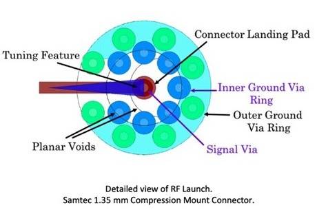
A launch is the mating structure that couples the electromagnetic energy in the connector to the PCB and consists of the connector, signal via and the via to the trace transition inside the PCB. Note that a connector’s launch is very different than a connector’s footprint. The differences are examined in this Wideband RF Launches white paper and further detailed in the article What is an RF Launch. If the launch is not designed properly for higher frequencies, energy can propagate through all the plane cavities beneath the launch, instead of being confined to the PCB layers.
Click to view E field animation:

5) How to obtain the widest possible de-embedding bandwidth?
The test fixture should have the lowest IL and RL possible over the frequency range of interest.
Insertion Loss: IL is directly correlated to the length of the fixture that needs to be de-embedded.
Return Loss: RL is heavily impacted by the performance of transitions (e.g. connector to PCB and DUT to PCB).
See “Minimizing Fixture IL” on page 5, and “Minimizing Fixture RL” on page 10. Note paper discussion regarding the physical distance that needs to be de-embedded for the different connector styles. With proper launch design, the impact of the RL of the connector launch can be minimized over the operating bandwidth.
6) Are there increased benefits to using ganged, compression mount connectors for 224 Gbps test?

Yes! A ganged connector, such as Bulls Eye® test assembly, reduces the physical area needed for multiple connections and can be placed directly next to the device under test. Minimizing the distance to the device under test will lower IL. And just like with all high frequency test applications, launch design is key to optimal performance.
Since channels are close to each other, a dense ground via structure within the launch can limit channel-to-channel crosstalk. Alternately, two interlocking rings of vias may be used.

Backer plates are also commonly used with ganged assemblies to prevent shorting or excessive capacitive loading on the bottom side of the PCB.
If a launch is not designed properly, a backer plate can form waveguides in the 60 to 70+ GHz range and be a source of significant crosstalk. Using launch design techniques mentioned in the published paper will remove this unwanted crosstalk. Or contact [email protected] for assistance.
Using 1 mm connectors on end 2 allows for greater IL-RL separation showing much lower RL for the device under test itself.
If the connector can be calibrated at the PCB interface, that is ideal. Otherwise, since coax cables have very low loss per unit length, they can provide good IL-RL separation to very high frequencies which in turn allows de-embedding algorithms to better reflect the performance of the device under test.
CONCLUSION
Read the published paper “Realistic Use Cases for Edge, Angled and Veritcal Launch Connectors Up to 100 GHz.” It will:
- provide a framework for choosing the right coaxial connector for high frequency applications
- examine how best to improve the signal integrity path from the test instrument to the device under test (DUT)
- provide essential techniques for de-embedding
It is entirely feasible that your 224 Gbps test system will perform well without needing exotic techniques.
For launch design assistance, or direction in selecting the right RF coaxial connector to improve signal integrity for your 224 Gbps test system, please contact [email protected] or [email protected].

SIMILAR RESOURCES THAT MAY BE OF INTEREST
- Download Samtec’s New, Precision RF Design Guide
- Wideband RF Launches: Literally Everything You Need To Know
- Check out Samtec’s gEEk® spEEk SI Webinar Series for tips and tricks on how to improve Signal Integrity for 224 Gbps
