112 Gbps PAM4 Rack-to-Rack Interconnect With Remarkable Results
Samtec Flyover® Twinax Cable assemblies allow designers to extend signal reach and density, enabling 112 Gbps PAM4 performance. Samtec Flyover systems are commonly used in mid-board applications, with a cable assembly connector located next to the chip. The signal path is directed to the front or back panel. Samtec Flyover also allows designers to go from one board to another as a flexible backplane architecture within a rack, and it can be used as a rack-to-rack interconnect.
For this rack-to-rack demonstration, we are using Alphawave’s AlphaCORE 100 Long Reach SERDES combined with Samtec’s mid-board to cable backplane application.
The Signal Path
JR Bonnefoy, Systems Engineer at Samtec, walks us through the signal path. Alphawave’s SERDES transmitter generates 31 bit PRBS data at 112 Gbps PAM4. These signals travel through about 1” of differential traces on Itera MT-40 PCB material to a Samtec Bulls Eye® high-performance test cable system, located opposite the chip on the back of the board.
The Samtec BE 70A, rated at 70 GHz, incorporates 6” of low-loss microwave cable terminated to 1.85 mm connectors. These 1.85 mm precision RF connectors are mounted on a Samtec SI Evaluation board.
The signals travel through another 2” of PCB trace to a NovaRay® high density board connector. Plugged into that connector is a NovaRay to ExaMAX® Flyover cable system. This incorporates 12” of 34 AWG Eye Speed® Ultra Low Skew Twinax Cable.
A one meter long cable connects one ExaMAX backplane socket to another, and at this point the return path repeats itself, back to the receiver. The signals go through another 12” long ExaMAX to NovaRay cable system, to the second Novaray SI evaluation board, then through 1.85 mm precision RF connectors on that board, and back to the Alphawave test board via the Bulls Eye BE 70A test point system.
The signal finally returns to the SERDES receiver where the data is collected and checked for errors.
The Results
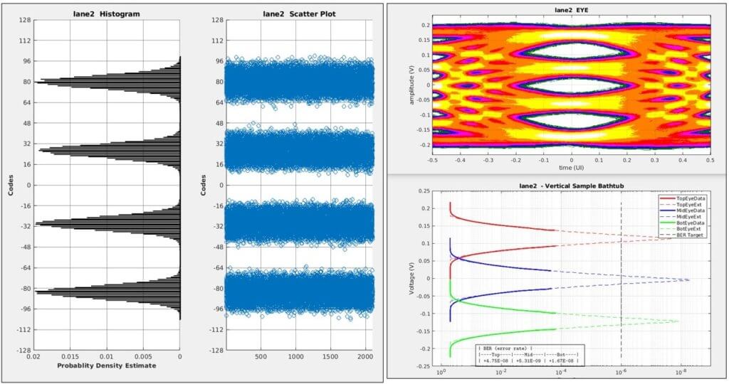
J.R. comments that the results are pretty remarkable. Using Alphawave’s user interface and analysis tools, we captured the PAM4 eye diagram at the receiver, after equalization. We can clearly see wide margins for all three levels of the PAM4 signaling.
The tool also plots a histogram of the symbol probability density, which shows four distinct distributions with very low ISI. The vertical bathtub curves show the expected bit error rate of this channel at approximately 1e-8 for each of the three eyes, and that is pre-FEC.
The Long and Winding Road: Rack-to-Rack
This is a long and complex signal path, representing a rack-to-rack type of connection. This demonstration has eight different connector interfaces and runs approximately 2.5 meters (98.4″).
The total loss for the entire signal path, including all cable assemblies and PCBs, is approximately 30 dB.
And the performance is well within specifications, by several orders of magnitude, providing the designer with plenty of margin.
As the data rate requirements increase, system designers struggle with propagating these signals through PCBs. Samtec Flyover solutions allow them to extend the signal reach and density by routing signals via ultra-low skew twinax cable instead of lossy PCBs.
If you have questions about this demo, email us at [email protected]