What Is A JTAG Connector?
Before we answer the question, “What is a JTAG connector?” let me first give you a brief overview of JTAG.
What is JTAG?
Joint Test Action Group, or JTAG, is the common name for IEEE Standard 1149.1. This standard defines a particular method for testing board-level interconnects, which is also called Boundary Scan. In short, JTAG was created to test for common problems, but lately, it has become a way of configuring devices. The JTAG hardware interprets information from five different signals: TDI (Test Data In), TDO (Test Data Out), TMS (Test Mode Select), TCK (Test Clock), and TRST (Test Report-optional).
The primary advantage of boundary-scan technology is the ability to observe data at the device inputs and control the data at the outputs independently of the application logic. Simple tests can find manufacturing defects such as unconnected pins, missing devices, incorrect or rotated devices on a circuit board, and even failed or dead devices.
The Joint Test Action Group was formed in 1985 to develop a method of verifying designs and testing printed circuit boards after manufacture. In 1990, the Institute of Electrical and Electronics Engineers codified the results of the effort in IEEE Standard 1149.1-1990, entitled “Standard Test Access Port and Boundary-Scan Architecture.” The JTAG standards have been extended by many semiconductor chip manufacturers with specialized variants to provide vendor-specific features.(1)
If you want to learn more, the end of this blog includes a couple of links to other articles about JTAG.
What is a JTAG Connector?

A JTAG connector is a pin header (i.e., a male terminal strip connector), usually on either .100” (2.54 mm) or .050” (1.27 mm) centerline. Common sizes are 10 pin (2 x 5), 14 pin (2 x 7), and 20 pin (2 x 10). JTAG connectors can be either through hole or SMT, and either shrouded or unshrouded.
If this sounds like a pretty loose standard, you’re correct. Actually, there is no single connector standard for JTAG. At the simplest level, a “JTAG connector” only needs four or five pins to operate a JTAG TAP. However, designers often incorporate ground and signal, and that’s where the number of pins increases.
Does Samtec Offer JTAG Connectors?
Of course we do! Otherwise, I wouldn’t be writing this blog. Samtec offers several JTAG connector options. Here are some of our most popular products:
- FTSH-105-01-L-DV-K: a 10-pin .050” pitch terminal strip, keyed
- FTSH-105-01-F-DV-K-P-TR: 10 pin, .050” pitch terminal strip, keyed, with pick-and-place pad, in tape and reel
- FTSH-110-01-L-DV-K: 20-pin .050” pitch terminal strip, keyed
- FTSH-105-01-L-DV-007-K: 10-pin .050” pitch terminal strip (Cortex Debug Connector; #7 pin is removed)
- FTSH-110-01-L-DV-007-K: 20-pin .050” pitch terminal strip (Cortex Debug + ETM Connector)
- TST-110-01-L-D: 20-pin, .100” pitch shrouded terminal strip (ARM Standard JTAG Connector)
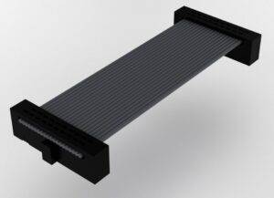
Suggested cable mates include:
- FFSD-05-D-06.00-01-N – 6” IDC Ribbon Cable Assembly
- FFSD-05-D-12.00-01-N – 12” IDC Ribbon Cable Assembly
Other Samtec products that are compliant with JTAG:
- EJH: .100″ shrouded IDC ejector header
- FTSH: .050″ terminal strip
- HHSC: .100″ JTAG ribbon coax cable assembly
- TST: .100″ shrouded terminal strip, mates with HHSC cable
- TSW: .100″ terminal strip
Here are a few links to other websites about JTAG connectors that may be of interest to you:
- Samtec’s JTAG page
- What is JTAG? (FPGA 4 Fun)
- Introduction to JTAG (All About Circuits)
- ARM Developer Overview of JTAG Connectors
- JTAG Connectors and Interfaces (All About Circuits)
- What is JTAG (Corelis)
(1) Wikipedia: JTAG
Where could I find pinout information on the iBMC JTAG plug on a specific device?
Hi Jonathan. You can email our support group [email protected] for help with this.