The Grounds Behind Grounding
A few weeks ago, I was working on an audio amplifier with my dad in the garage. As I began to wire it up to test a new set of speakers we had bought, I received a nasty shock when plugging in an older, frail patch cable. Now, something didn’t seem to add up here; I had used this cable before on my equipment and never had problems. However, in this instance, something was different; the older tube amplifier we were using had no ground.
In today’s industry and even in household use, electrical grounding is always a topic of discussion. Whenever a storm or an unexpected surge hits, it is grounding that protects us and our equipment from harm. However, many electronics, like my dad’s old tube amp, were not always designed that way.
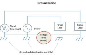
The need for an electrical ground, or common, was raised primarily in the year 1837 by inventor Samuel Morse. As people began sending and receiving telegraphs through transmission and receiving lines, scientist Carl Steinheil discovered a more efficient way to communicate – use Earth ground as the return line.
However, problems arose as other sources like power systems, railways and even lighting strikes induced power currents in the Earth. Since the earth has finite impedance, any current flowing through it produces unwanted voltages in the form of noise. The electrical noise varied with changes in soil moisture, how well the ground system is maintained, power load changes and other variables.
This phenomenon was one of the first observation of common impedance coupling. When signals and power share the same current return path (ie. earth ground), tiny voltages drops can occur over any common impedance that may occur. This noise is called crosstalk. This caused serious problems for telegraph and early telephony systems as illustrated below.
As time went on, grounding developed from a common conductor reference, to the safety precaution we have come to appreciate today. From the fuse boxes in our homes, to some of the smart devices we use daily, grounding has protected both us and our electronics from serious damage. In addition to providing us peace of mind, electrical grounds have also greatly contributed to the industry of semi-conductors and SI (Signal Integrity).
In almost every PCB or microelectronic device on the market today, there is an electrical ground in the form of a ground plane. A ground plane is a thin copper layer within the PCB acting as a common reference for all parts of a circuit. Unlike older circuitry and schematics, with this design, the entire system would be referenced to the ground plane, thus eliminating the need for additional wires or specific grounding points.
Using a ground plane not only references the PCB, but also helps in reducing spikes in current or voltage just as it does in power systems. Unfortunately, there are also potential issues that need to be considered when designing and using a ground plane in your next circuit.
Problems and Solutions
Just as was the case with early experiments in grounding, crosstalk is a serious concern. Unlike DC currents that travel directly from source to load, high-frequency current return paths vary. This may not seem to be an immediate issue when looking at the top of PCB. All your lines are nicely etched and transmit electrical signals directly.
However, one must remember the example of the telegraph: that is only the signal line. The return line consists of currents on the ground plane. Just as a telegraph message could become distorted by sharing a common ground with other devices, the same goes for high-frequencies in PCBs.
Due to the fundamentals of electro-magnetism, the high-frequency signal returns follow the copper traces on the opposite side of the board to complete the signal path. Why do we care? It turns out that the exact same physics which gave rise to noise 100 years ago on telegraph systems leads to noise in modern high-speed digital circuits.
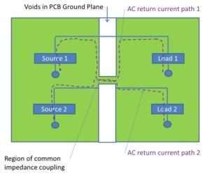
Crosstalk from common impedance coupling risks distorting and undermining SI when enough copper traces are compounded into a small area with gaps in the ground plane. Essentially, it is like forcing many people through a narrow door, someone is bound to get stuck.
This is illustrated below. Instead of high-frequency signal #1 returning from load to source, high-frequency signal #2 could interfere and cause distortion. Now imagine this happening thousands of times on PCBs very high processing power: it can cause quite a lot of noise.
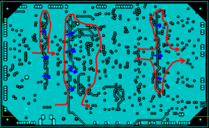
The key to a problem-free ground plane lies in being uniform and removing gaps or voids. In this way, the signal will be able to trace back to its point of origin, never intercepting other signals, even though another trace may be a fraction of a millimeter away (illustrated below). Samtec has and continues to employ various methods to promote Signal Integrity through ground planes in our products and Design Centers.
Mezzanine Strips Feature Integral Ground Planes
Samtec Mezzanine Strips have integral ground planes allowing for a large variety of mounting options as well as acting as interconnects. This serves a dual purpose; it provides both a reference ground to single boards, as well as assuring proper grounding when connecting between multiple.
Depending on the need, Samtec offers a variety of solutions to ensure proper grounding.
Our Q Strip family offers integral ground and power planes for AC/DC use at 28 Gbps as well versatile stacking heights and I/O compatibility per board. This allows the user to both ground the board as well as any DC devices used in tandem with it, providing the protection necessary.
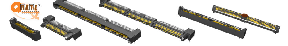
The Q Rate family of interconnects provides reliable SI and positioning as well. Through use of our Rugged Edge Rate contacts and a diverse array of positioning, Q Rate allows for minimal board real-estate while acting as a solid ground. Both of these families act as reliable grounding planes for single board applications.
Optimized for 100 Ohm systems, our Q Pairs interconnects are crucial for Signal Integrity in high frequency, heavy processor devices requiring multiple boards.
By using differential pairs when mated, the Q Pair and Q Strip families eliminate any noise that could be detected by responding to the difference in the original signal and compensating as necessary. These board-to-board connectors assure multiple options for mating in a variety of interconnects and cables.
Like the rest of our Q Series line, they offer multiple ground planes and low stacking height, protecting against any interference in high-frequency environments where multiple PCBs may be used.
Electrical grounding has come a long way since the 1800s. It has made history innovating new technology, given us and our devices protection, and continues to ensure proper Signal Integrity now and into the future. Just as the saying goes, the semiconductor industry will “continue to reach for higher ground”. Pun intended.