Power Interconnects 101: Understand Creepage and Clearance
Ongoing trends to reduce PCB size and increase density become a design challenge when these smaller, denser PCBs incorporate high voltage circuits. Designers are usually trying to reach UL and CE 61800-5-1 specs [1] that call out creepage and clearance distance given material grade, working voltage, and pollution degree. Creepage and clearance are about safety and meeting regulatory standards, regardless of the system design.
A recent white paper aims to discuss and define the terms associated with the safety requirements of creepage and clearance and a brief discussion of comparative tracking index (CTI). The results of several related experiments are also presented to demonstrate the concepts discussed as they relate to interconnects.
Creepage & Clearance are Important
Creepage and clearance are product safety terms and requirements for many types of products, assemblies, and components. Regulating agencies such as IEC, UL, and CSA have very specific product application guidelines and requirements that must be met in order to sell products in many countries.
Creepage and clearance standards help to ensure safe operation, reducing the risk of electric shock or other injuries to the end users as well as reducing fire hazards. These standards are also designed to protect other components in close proximity to those being rated/tested to help avoid propagation of a failure throughout a system. This discussion will be related to power interconnects, printed wiring boards/printed circuit boards (PWB/PCB), and cable assemblies.

What is Creepage?
Creepage is the linear distance along all of the insulating surfaces between two electrical conductors (see Figure, right ). As far as electrical measurements are concerned, the result of this parameter is basically the equivalent of a surface insulation resistance measurement (SIR or IR). Notice that since this is the total surface distance between the conductors, it is considerably longer than the clearance distance of the same contacts.
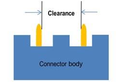
What is Clearance?
Clearance is the distance between two electrical conductors through the air. In the simplest terms, it is the distance a spark has to travel, like in a dielectric withstanding voltage (DWV) breakdown test (see Figure below).
Avoiding Damage from Electrical Arcs
The full white paper explains what kind of damage electrical arcs can cause and how to avoid damage in your next design. It also covers industry standards and specifications, test methods, and comparative tracking index.
Service and Support

Samtec has multiple resources that can help you locate a connector system that will meet creepage and clearance specifications for power products. First, creepage and clearance specifications are listed on the product’s catalog page.
Alternatively, Samtec’s Solutionator parametric search tool finds Samtec socket and terminal sets based on your design requirements. Two of the search parameters are creepage and clearance. To use: open Solutionator and select the “Additional Filters” box under “Search Options” and then enter the required creepage and/or clearance to see the matched Samtec products [2].
Samtec can also selectively load contacts to achieve customer-specific creepage and clearance requirements. This is a common application to meet both creepage and clearance distances. For additional support with this, contact [email protected].
References
[1] IEC 62368-1, Audio-video, information and communication technology equipment, International Electro technical Commission, Geneva, Switzerland
[2] Samtec Solutionator