There comes a time when every design must enter production. However, the path that any item takes from initial concept to final production is a complicated one, and it is very rare that any device makes it through this process unchanged.

It would be great if there were no limits imposed by schedules or budgets. To paraphrase US soldier Hal Moore, “Unlike in baseball, three strikes and you are not out. There is always something else you can try…” Moore was talking about leadership, but the same is true of electronic design. But most of us do not enjoy the luxury of unlimited redesigns. At some point, a decision needs to be made, even if the design is not yet perfect.
There was a time and place in which engineers did have this freedom. The early days of space agency NASA fostered this “engineering for its own sake” approach, and its designers could pursue the ultimate flying machines without regard to budgets or timetables. The excellent book “Apollo” by Charles Murray and Catherine Bly Cox describes this engineering paradise, before the tempo of the space race made finding solutions a matter of urgency.
Design or Production?
Before the era of computer aided design (CAD), when engineers would use pencil and paper to create the next generation of equipment, there was a definite point at which production commenced. As soon as the first metal was cut, making changes became significantly more difficult. Any change before this point was a pen-and-paper exercise, although these changes might have knock-on effects for other elements of the design.
With the advent of CAD, making changes during the design phase became simpler. The more sophisticated software available today assists these changes and can manage (or at least highlight) any unintended consequences. Modern software goes further, and now provides far more capabilities than simply assisting with design. Simulation software can replicate electronic functionality, allowing engineers to test a virtual version of their design before a single wire is cut. Mechanical testing can be simulated with finite element analysis (FEA) which can predict how a product will react to real-world forces such as vibration, heat, and fluid flow.
The very definition of production has also changed. CAD software can interface with 3D printing equipment to allow complex prototypes to be created and tested quickly. If a change is required, the cost and delay imposed by making the next version is minimal and, with access to a physical sample, the engineer can be confident of their design before series production begins.

Connector Design
This is particular of interest when one comes to consider connectors. As much as I hate to admit it, connectors are not the most important element in any design. From the simplest power circuit to the most complicated data centre, connectors are just part of the infrastructure, allowing the transmission of signals, power or data from one element to another. They are therefore rarely selected during the early stages of a design.
This fact may not have been that important during the early days of microelectronics. In the 1970s and 1980s, almost all components on the printed circuit board (PCB) would have been manufactured to match the 0.100” (2.54mm) pitch that was commonly used at the time. Connectors, along with passive and active components, were based upon this common form factor, allowing an element of modularity. If all components use the same generous pitch, it is relatively simple to exchange one component for another, and there is ample room between terminals for the all-important traces along the surface of the PCB.
Over time, all electronic components have become progressively smaller, allowing the modern miniaturised devices with which we are now so familiar. It would be impossible to design a practical smartphone with the electronic components of the 1970s.
Connectors have also become smaller over the years to keep pace with the designs of which they are so vital a part, but their required performance places limits on how small they can be. If a connector is to carry significant electrical current, then its contacts need to be of sufficient size to provide a low resistance. The contacts of a connector that handles high voltage must be physically separated to prevent unwanted arcing.
Did you leave enough room…?
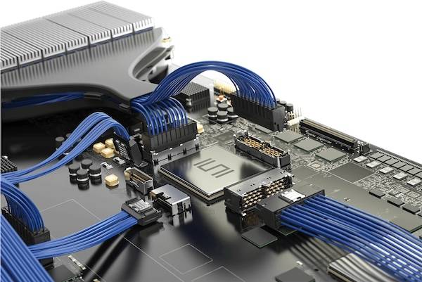
In addition to their electrical requirements, connectors are amongst the few elements in any design that must withstand the rigours of the outside world. Unlike semiconductors and other PCB-mounted components, this places mechanical demands on their form. If a connector needs to be protected from the elements or is to be handled regularly, it must be designed with this in mind. Even the latest Samtec ultra-fine pitch connectors that are intended for use in today’s miniaturised devices need to be robust enough to withstand day-to-day use without damage.
Make Room for Connectors
All these competing demands result in a connector that is often larger than a designer might like. It is easy for the designer to underestimate the amount of space that needs to be allowed or overestimate the capabilities of the connector itself. The designer might be surprised to find that the connector may well be one of the largest components that they must employ.
To help customers at every stage of the design process, Samtec has a suite of online tools to create solutions and streamline your product, all openly available for use & download. Learn more about how our tools can help you here.


Leave a Reply