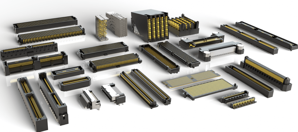
With so many connectors available there is almost an infinite number of combinations from which to choose. To the untrained eye, many look the same but an experienced engineer will quickly tell you that this is certainly not the case. Connector selection can be a challenge, but do not fear — with just a little knowledge you can find the right solution.
All Connectors Are Not Created Equal
The #1 consideration when selecting a connector system is the quality level required for your application. It’s possible to get almost any connector for just pennies, but while many of these parts can look good on paper, unfortunately, the quality can be hit or miss. Connector issues can be very costly long term (field returns costs), but some investment up front can provide savings across the product life cycle. Click here to find out more about Samtec’s Compliance and Quality commitments.
It would be great if we could just visually inspect a connector to check for quality issues, but it’s not that simple. Why not, you ask? Well, a classic example would be plating specifications. A “gold” connector is a gold connector, or is it? Commonly “gold” parts may not have any other specification or are described as gold flash. From some sources, this could be less than 1 micro inch of gold. This plating type can wear through quickly leaving the under plate to make contact, which significantly reduces connection reliability and leads to uncontrolled increases in connector resistance.
Finding A Path
As with any complicated problem, the easiest solution is to break it up. So how do we do this for connectors?
To start, it’s best to limit the scope in order to determine the connector type required (PCB/Board-to-board/Cable assembly, etc.) For the purposes of this discussion let’s assume we need a PCB level connector and explore the associated issues. These are the most common type of connectors used and almost every product has at least one or two PCB level connectors.
Breaking down the connector into bite sized pieces helps identify the traits we need and on what we should concentrate. Samtec’s Solutionator online tool is also a helpful way to quickly filter the below traits in order to find a mated set that fits your application needs.
- Pitch (2.54 mm, .100”, etc.)
- Operating environment (high vibration, high mating cycles, etc.)
- Connector use (for example, power, data, RF)
- EMI/EMC requirements
- Mate type (socket or pin, stack height if connecting two boards, etc.)
- Plating type (tin or gold)
- Retention force (how easily the connector can be removed from the socket)
- Mating orientation (for example, right-angle, straight, shrouded/pin only, etc.)
- Solder type (surface mount or through-hole)
There are usually other design-specific considerations that may further influence some of these. A common example would be a size constraint limiting the housing type of the connector.
Narrowing The Choices Further
Let’s look at these considerations in a little more detail.
Connector Type
Connector application, pitch, mating type and orientation are simple to define. Mating type should be chosen to meet the application, like board-to-board, cable-to-board or interface specific (USB). For the pitch of a connector it’s typical to match current board pitch, and for ease-of-processing, most designers specify the biggest pitch their board space allows. If in doubt, selecting a common pitch, such as 2.54 mm, is recommended. A high-speed or RF connector will have different requirements than a power connector, so choosing the right connector type for the job is the first step.
Manufacturing Specifics
Manufacturing considerations should be defined by your board technology. If surface mount technology (SMT) is used, there are a few questions to consider: How will the part be placed? Does the connector have pick-and-place machine mounts? Does it come on tape and reel?
For through-hole technology, we should consider which process will be used e.g. wave solder or paste-in-hole (also called pin-in-hole and pin-in-paste). If the latter, then the connector must withstand a surface mount process, so it will need more substantial polymers and glass reinforced plastic parts similar to SMT.
Environmental Considerations
If extreme vibration and g-force immunity are required then press-fit may be considered, but for most commercial applications that could be overkill. This does not mean retention force and vibration immunity should be ignored. It’s easy to forget that manufacturing isn’t the end for commercial products. They have to survive transport from the manufacturing location to the end customer. This can involve a high degree of vibration and any non-latched connectors should be rated or tested for retention in these conditions. Additionally, this is where the plating is put through its paces and most fretting will occur.
Connector Construction
As previously discussed the plating specification of the connector should match its use. It’s easy to assume a high-cycle connector (e.g. a USB) must have an extremely thick plating. This is not always the case since many insertions equal many wipes of the contacts. In this case, gradual oxidation may not ever become an issue. But using the same connector inside a product where it gets plugged once and never re-inserted could be prone to problems. If required use is in harsh operating environments (high temperature/vibration), this will further limit the choice of materials and connection methods.
At Samtec, we provide scalability from lower to higher quality platings as required. It is recommended to pick one suitable for the application – gold for higher quality (and cost), and tin for lower cost and solderability. How do you find this information? Most interface specifications will recommend a connector, which is a good guideline to follow. If no recommendation is available, then here’s a good rule – for most connectors 15 micro inches of gold is sufficient and 30/50 micro inches could be excessive.
In addition to plating, using multiple points of contact can significantly reduce the likelihood of failure. Any power connector over a few hundred mA will benefit from multiple points of contact connector such as Samtec’s Tiger Claw™ contact system. If available, using multiple power and ground connections can give the same benefit — using both builds redundancy.
For more about Samtec’s contact systems and their flexibility to meet your application needs, visit samtec.com/contact-systems
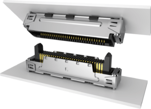
A Connector’s Mate
Any connector is only as good as the connector to which it will mate. Surprisingly this is easy to overlook. One-half of a design can be over engineered leaving its mate to fail in the field.
While on the topic of mating, it is important that connector metals are of a similar type. Mixing tin and gold is a bad idea because undesired reactions, like oxidation, could occur since the metals have different energy levels. The rule of thumb is like-with-like: tin with tin and gold with gold.
Electromagnetic Compatibility
Application specific EMI or EMC requirements may require shielded interconnects. Using shielding within the interconnects can reduce emissions and component count from the design, with less filtering being required.
Testing Is Key
Testing the design is the only sure fire way of knowing the connector is suitable for its purpose. Product environmental and vibration testing is a good “yard stick” and will often reveal concerns before they become an issue out in the field. Connector resistance after a number of mating cycles should also be measured. This is typically a fairly low resistance that requires specific equipment such as an LCR meter. Depending on volumes though, this may not be commercially viable and therefore another good option is to rely on vendor testing.
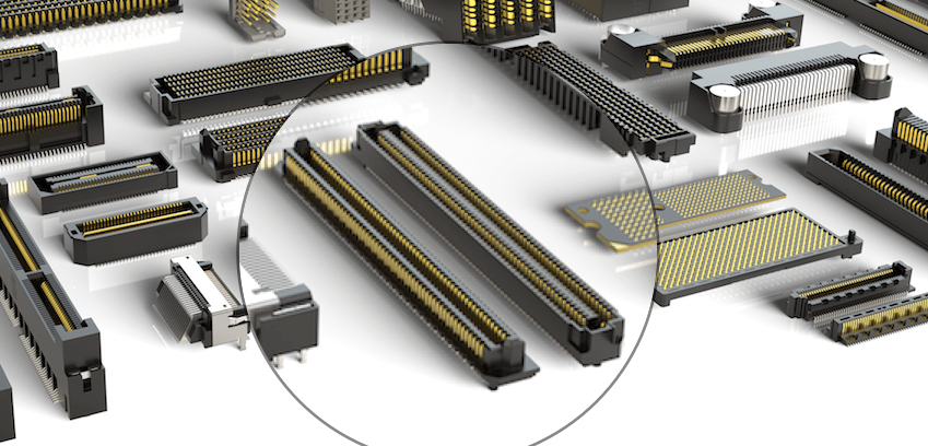
For example, Samtec’s SFM Series, (.050” pitch Tiger Eye™ Socket Strip) features a multitude of test reports available for a mated connector set. A few of the reports available include:
- SFM/TFM – Design Qualification Test Report (3µ” Au)
- SFM/TFM – 6.35 mm Mated Height High-Speed Characterization Report
- SFM/TFM – 11.81 mm Mated Height High-Speed Characterization Report
- SFM/TFM – Mixed Flowing Gas (10 Years of Life)
- SFM/TFM – Extended Durability (1000 Cycles), Tiger Eye™ Contact
Both plating and mating cycle test are included giving a good indication of connector performance after 1000 mating cycles. This testing can give confidence where there is no business case for additional testing.
Over Design Costs Money
With quality as the #1 consideration when selecting a connector, it is easy to over design a connector. This can cause substantial blows to the bottom line. Designing in 50 micro inches of gold into a connector that mates with a tin counterpart will result in a very expensive and possibly unreliable design. It would be more reliable to choose a tin based plating and save money in the process. Looking at the whole system and its requirements should give sufficient insight into choosing a connector that is just right for your application.
Final Thoughts
Connector selection often boils down to the dilemma between cost and quality. It is almost always best to err on the side of caution and provide some over design, but keeping this within limits will help ensure the final product is profitable.
To help make your design process easier, Samtec provides 24-hour free Sudden Samples. Check this out to learn how to request your free sample.