A working demonstration of the Apollo communication system — the original Apollo S-Band communication hardware that was used in the Apollo moon missions in the 1960s and early 1970s — was on display at DesignCon 2023.
Marc Verdiell, CTO of the Samtec Optical Group, walks us through the setup. Marc is part of a team that is restoring this Apollo communication equipment to its original functional state. All equipment is on loan from private collections.
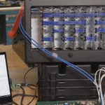
The system operated at 2.1 GHz and was called the Unified S-Band Link, or USB for short. It consolidated voice, data, ranging, and television signals on three S-Band carriers, and was also able to transmit live television from lunar distances. It was a space communication tour de force in the mid-1960s, being all solid-state except for the power amp.
A powerful (20 kW) phase-modulated uplink carrier, at an atomic-controlled frequency of 2.1064025 GHz, was sent to the spacecraft. It carried a digital pseudo-random sequence used for ranging, and subcarriers for voice and data.
The spacecraft transponder receiver phase-locked onto the uplink carrier, now received at a different frequency because of the doppler shift. The transponder synthesized the downlink frequency from the uplink using a 240/211 ratio. It then retransmitted the received pseudo-random ranging code on it, along with voice and data from the spaceship on their own subcarriers.
Another free-running FM downlink carried live TV and recorded data. That led to the somewhat complicated spectra. The transmitted antenna power was only 11 W per carrier.
On earth, the receiver locked on the transponded frequency and calculated speed using the doppler shift. The distance was computed by digital correlation of the turnaround time of the ranging code, using a special-purpose real-time computer.
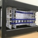
Most of the spacecraft’s microwave communication electronics were on display. This included the NASA ground test equipment which was used to make a test version of a ground station. It consists of the up-data link, PM transmitter and receiver, FM receiver, and interface simulator.
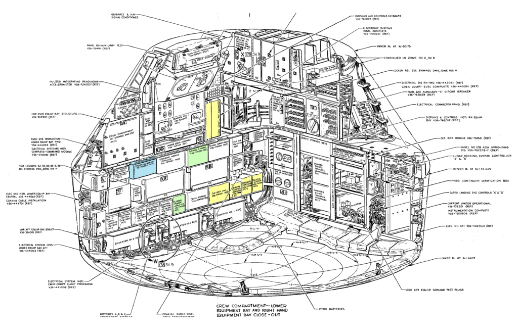
There was also equipment that was in the Command Module, including the USBE transponder, the traveling wave amplifier, the pre-modulation processor, the up-data link, PCM telemetry, central timing equipment, and the audio center.
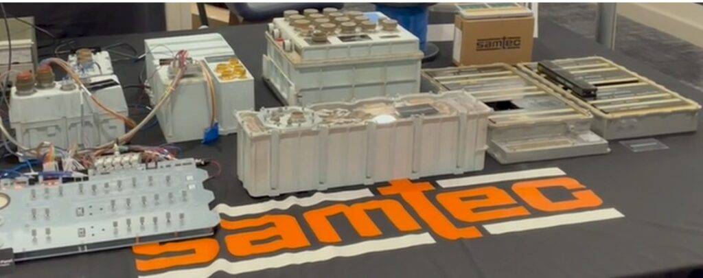
The vidicon TV camera is not the NASA original, but it is a fair representation of the size of the actual one.
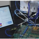
The system also included some non-NASA equipment to help run and monitor the setup. This included the 400 Hz 3-phase power source, a spectrum analyzer, a frequency meter, and a period-correct TV monitor.
You can follow the restoration progress on the “CuriousMarc” channel on YouTube at https://www.youtube.com/curiousmarc
If you enjoyed this blog …
Leave a Reply