In a recently published white paper, “Array Connectors for Mixed Signal Multi-Channel RFSoCs up to 8 GHz,” Samtec engineers describe the research, development, simulation, and measurements performed in a project to design the optimal breakout region (BOR) for the use of array connectors that simultaneously carry analog, digital, and power signals in an RF environment, as a replacement for traditional compression mount and threaded PCB connectors. The results show that it is possible to route high-frequency, high-isolation RF signals as well as digital and power signals through a single connector.
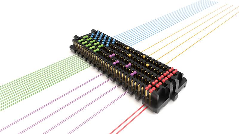
Samtec Analog over Array technology supports analog differential pairs and single-ended signals as well as digital and power signals.
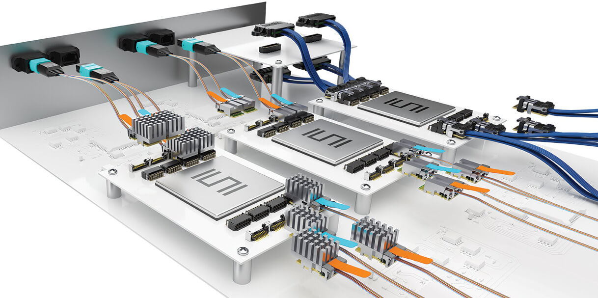
System on Chip (SoC) implementations with integrated data converters and RF front-end subsystems are being deployed in 5G/6G, phased array radar, SATCOM, FPGA cards, and test & measurement architectures. The use of these RFSoCs challenges the traditional approach of handling the RF signals with compression mount and threaded PCB connectors. A simple alternative, using multiple ganged connectors, still puts strain on form factor, weight, and financial budgets, especially as high-frequency RF channel counts increase in these SoC-based systems.
The first step of this research and development project was simple, as Samtec already had existing array connectors for high-performance, high-speed digital signaling. Adapting this technology for RF applications required the development of specific PCB stack ups and launch optimizations in order to achieve the differential crosstalk and return loss performance required for frequencies up to 8 GHz and beyond. The paper describes the research, development, simulation, and measurements performed to design the optimal breakout region (BOR) for the successful use of array connectors in an RF environment— how to carry analog, digital, and power in one connector.
Performance Requirements
The design targets identified for this mixed-signal connector array project were based on the specifications from existing RFSoCs, such as the AMD Xilinx Zynq and included:
- 8 GHz bandwidth
- 50 ohm system impedance for single-ended; 100 ohm for differential
- Return loss of -12dB up to 4 GHz; -10 dB up to 8 GHz
- Crosstalk isolation between channels: -69 dBc to 4 GHz; -63 dBc to 8 GHz
This work took an unconventional approach to an optimized breakout design in terms of materials, launch, connector pin field, and differential ground pattern. Because of that, a currently available 560-pin single array connector can support up to 26 differential RF signals. You can read the entire white paper to see the design choices, including microstrip vs stripline; the comparison of an optimized BOR for digital vs RF signals; performance analysis, including NEXT and FEXT isolation, return loss, and VSWR; results, conclusions, and future work. A reference design for SEARAYTM includes recommended pin mapping as part of a full characterization report. For more information on PCB materials selection, stackup, and launch optimizations for your design, email [email protected].
Also See
Technical Resources Help with Interconnect Design – The Samtec Blog
Leave a Reply