Samtec has more ways to connect two or more boards than any other interconnect provider. This blog discusses board stacking interconnects that are a little different than your standard mezzanine configuration, but offer solutions when you have design constraints that can be difficult to work around.
Connect Three (or more) Boards
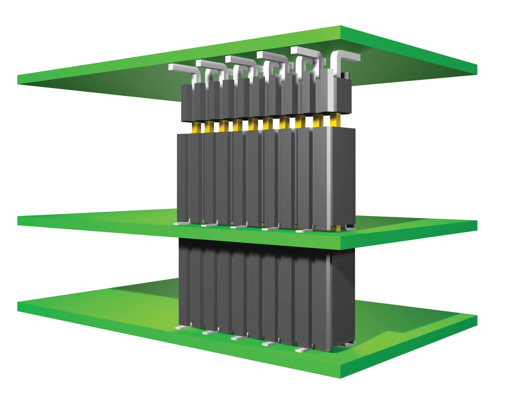
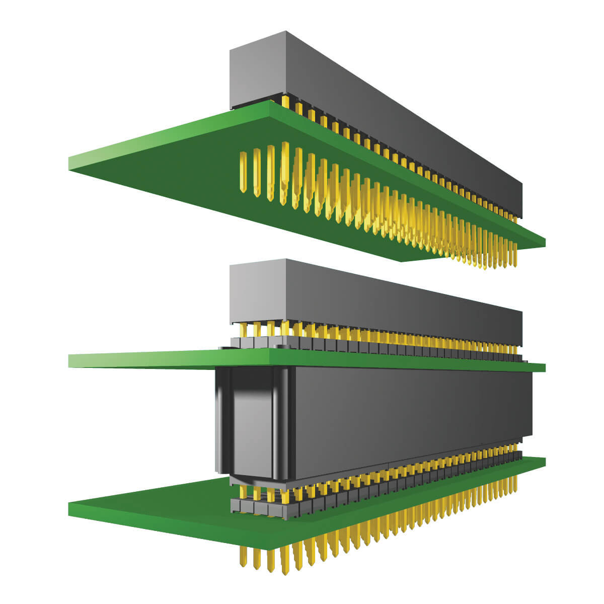
A board stacking strategy employed by many Samtec customers is “pass-through.”
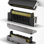
A common pass-through application is connecting three pcbs (or more) with one terminal strip and two sockets with pass-through contacts.
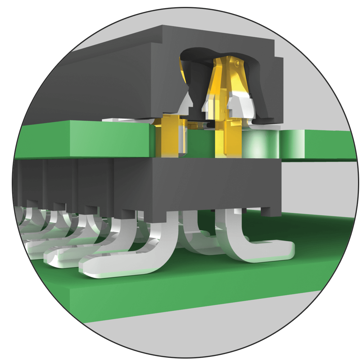
To make this work the socket must have an open-ended contact that allows the mating pin from the terminal strip to pass all the way through the contact. In other words, the terminal strip pin can’t bottom out in the contact.
This design is used when one of the boards is used to modify, upgrade, or retrofit the system configuration. Connecting three boards is also popular when space constraints require smaller boards, or if components can only be placed on one side of the pcb.
Unplated through holes are drilled directly under the socket strip contacts. Pins from the terminal strip pass through the socket, through the pcb, and eventually plug into a second socket on a third pcb.
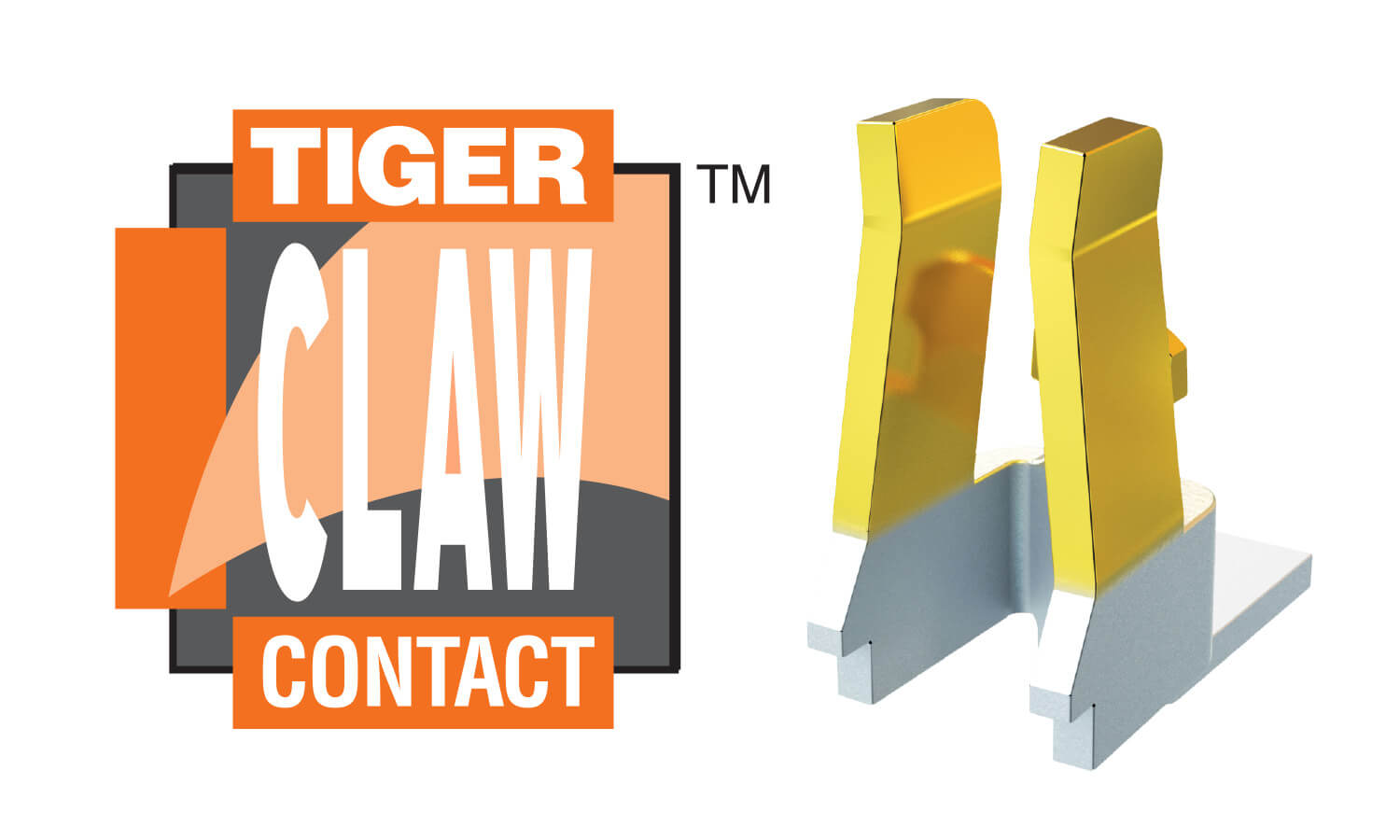
The Samtec Tiger Claw is one contact designed for pass-through applications. Below is a chart identifying popular Tiger Claw products.
Popular Tiger Claw Products
| Pitch | Application | Socket | Terminal |
|---|---|---|---|
| 1.00 mm | Board Stacking | CLM | FTM FTMH |
| 1.27 mm | Board Stacking | CLP | FTS FTSH |
| 2.00 mm | Board Stacking | CLT | TMM TMMH |
| 2.54 mm | Board Stacking | SSM BCS | TSM TSW |
Bottom Entry
A second pass-through application is connecting two (or more) boards on a parallel plane, but instead of making a “sandwich” with two pcbs and two connectors, the motherboard with the terminal strip is plugged through the bottom of the daugthercard with the socket strip.
This design is used if the application requires the user to view a device, or have access to components, on the daughtercard.
In other words, the components are not hidden from sight on the inside of two boards that are mated in a traditional fashion. Bottom entry is also used if the application requires two boards which must fit into a low profile space.
Self Nesting
With self-nesting interconnects, sockets with long, square tails pass through pcbs and plug into one another to form a complete system.
For example, tails from socket strip #1 pass through pcb #1 and plug into socket strip #2 on pcb #2. The tails on socket strip #2 can then pass through pcb #2 to socket strip #3 on pcb #3, and on and on.
Sockets are terminated to each board with either press-fit pins, or with traditional through-hole pins that are hand-soldered to the pcb. Self-nesting allows modular designs, and is ideal for embedded computers, industrial, and military applications.
The concept has been accepted by PC/104-Plus™ for embedded PC applications. The benefits of self-nesting are lower component costs since you do not need to purchase the mating terminal strip, and virtually endless stacking possibilities to expand the system as needed.
But Wait. There’s More!
Here are some related links that may be of interest:
- Selecting The Right Contact For Your Board-to-Board Interconnect System
- Board Stacking Picture Search Tool
- Comprehensive Picture Search Tool
- .100″ (2.54 mm) Pitch Board-to-Board Interconnects
- 2.00 mm Pitch Board-to-Board Interconnects
- Samtec PC/104-Plus Products
- Samtec PC/104™ Systems
- Samtec PC/104 Products